93
ADVANCED USER GUIDE
Commander SX
IP66/Nema 4X variable speed drive
MENU 10: DRIVE STATES AND DIAGNOSTICS
CONTROL TECHNIQUES
3854 en - 03.2008 / b
: Direction running
Adjustment range :0 or 1
0 (Forward) (Fd): The post-ramp reference is negative
(reverse).
1 (Reverse) (rSe): The post-ramp reference is positive
(forward).
Note: Do not take this parameter into account with the motor
stopped.
and :Not used
: Motor overload alarm
Adjustment range :0 or 1
0 (Disabled) (OFF):
1 (Enabled) (On):
This parameter is at 1 when the motor current exceeds 110%
of the programmed motor rated current and the cumulative
overload exceeds 75% of the overload capacity of the motor.
If the motor current is not reduced, the drive will trip on fault I
x t, or will reduce the current automatically according to the
protection mode configured in 4.16.
: Drive overtemperature alarm
Adjustment range :0 or 1
0 (Disabled) (OFF):
1 (Enabled) (On):
This parameter is at 1 when the measured temperature of the
IGBTs is higher than 100 °C, or when the drive automatically
reduces the configured switching frequency, owing to
overheating of the heatsink.
: Drive general warning
Adjustment range :0 or 1
0 (Disabled) (OFF):
1 (Enabled) (On):
This parameter is at 1 when at least one of the alarms 10.12,
10.17 or 10.18 is activated.
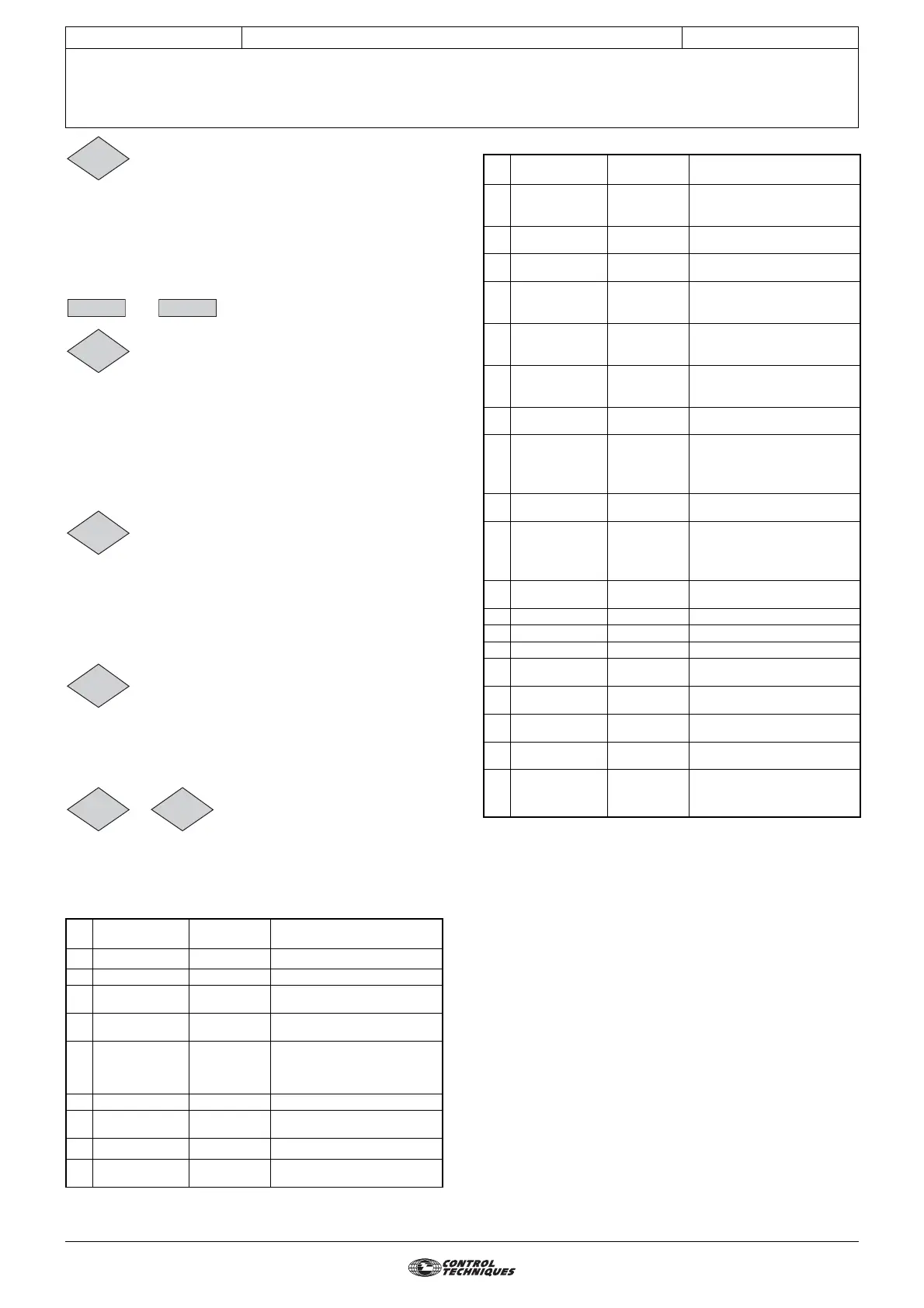
to : Last 10 trips stored
Adjustment range :0 to 54
Contains the last 10 drive trips.
10.20: Indicates the most recent trip.
10.29: Indicates the oldest trip.
The possible trips are:
No. LCD display LED display Reason for trip
1 DC UnderVolt UU DC bus undervoltage
2 DC over volt OU DC bus overvoltage
3 Over current OI.AC Overcurrent at drive output
4 Brak. IGBT OI.br
Braking IGBT transistor
overcurrent
6
Out Ph. loss
ph.AC
Loss of a motor phase with
brake enabled
7 Over speed OSP Over speed
19 Brak. resist. it.br
Braking resistor overload I
x t
20
Motor I
2
t
it.AC Motor overload I x t
21 Th IGBT U Oht1
IGBT overheating detected
by internal sensor
10.14
10.15 10.16
10.17
10.18
10.19
10.20 10.29
22 BR over heat Oht2
Internal braking resistor
overheating detected by
thermal sensor
24 Motor PTC th
Motor thermal sensor has
tripped
26
24V
OVERLOAD
O.Ld1
Overload on the +24V
power supply or digital
27 ADI1 loss CL1
Loss of the current
reference on analog input
ADI1
28 ADI2 loss CL2
Loss of the current
reference on analog input
ADI2
29 AIO3 loss CL3
Loss of the current
reference on analog input
ADIO3
30 COM loss SCL
Loss of serial link
communication
31 EEPROM fail. EEF
EEPROM trip or transfer
problem with XPressKey
(drive and key version
different)
33 Stator res. rS
Trip during measurement of
the stator resistance
34 Fieldbus loss Fbus
Disconnection of the
fieldbus during operation or
error detected by the bus
option
35 Sec. disable Secd Secure disable input trip
36 U sign. loss Enc1 Loss of channel U
37 V sign. loss Enc2 Loss of channel V
38 W sign. loss Enc3 Loss of channel W
41 User 1 tr01 User trip 1 via digital input
42 User 2 tr02 User trip 2 via digital input
43 User 3 tr03 User trip 3 via digital input
44 User 4 tr04 User trip 4 via digital input
45
to
51
User 05
to
user 10
tr05
to
tr10
User 5 trip via serial link to
User 10 trip via serial link
No. LCD display LED display Reason for trip