Menu 4
Parameter
structure
Keypad and
display
Parameter
x.00
Parameter
description format
Advanced parameter
descriptions
Macros
Serial comms
protocol
Electronic
nameplate
Performance RFC mode
104 Unidrive SP Advanced User Guide
www.controltechniques.com Issue Number: 10
Closed-loop vector and Servo
The proportional gain Kp (Pr 4.13) is the most critical value in controlling the performance of the current controllers. Either the value can be set by
auto-tuning (see Pr 5.12), or it can be set by the user so that
Kp = (L / T) x (Ifs / Vfs) x (256 / 5)
Where:
T is the sample time of the current controllers. The drive compensates for any change of sample time, and so it should be assumed that the
sample time is equivalent to the lowest sample rate of 167μs.
L is the motor inductance. For a servo motor this is half the phase to phase inductance that is normally specified by the manufacturer. For an
induction motor this is the per phase transient inductance (σLs). This is the inductance value stored in Pr 5.24 after the auto-tune test is carried
out.
I
fs
is the peak full scale current feedback = Kc x √2 / 0.45. Where Kc is the current scaling for each size of drive.
V
fs
is the maximum DC bus voltage.
Therefore:
Kp = (L / 167us) x (Kc x √2 / 0.45 / Vfs) x (256 / 5)
= K x L x Kc
Where:
K =
√2 / (0.45 x V
fs
x 167μs) x (256 / 5)
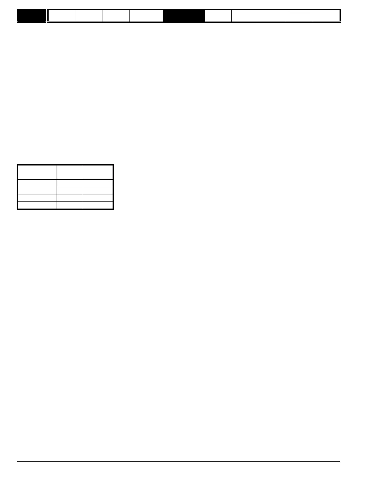
There is one value of the scaling factor K for each drive voltage rating as shown in the table below
The integral gain Ki (Pr 4.14) is less critical and should be set so that
Ki = Kp x 256 x T /
τ
m
where
τ
m
is the motor time constant (L / R).
R is the per phase stator resistance of the motor (i.e. half the resistance measured between two phases).
Therefore
Ki = (K x L x Kc) x 256 x 167us x R / L
= 0.0427 x K x R x Kc
The above equations give the gain values that are calculated by the auto-tune system and these should give the best response at all switching
frequencies with minimal overshoot. If required the gains can be adjusted to improve performance as follows:
1. The integral gain (Ki) can be used to improve the performance of the current controllers by reducing the effects of inverter non-linearity. These
effects become more significant with higher switching frequency. These effects will be more significant for drives with higher current ratings and
higher voltage ratings. If Ki is increased by a factor of 4 it is possible to get up to 10% overshoot in response to a step change of current
reference. For high performance applications, it is recommended that Ki is increased by a factor of 4 from the auto-tuned values. As the inverter
non-linearity is worse with higher switching frequencies it is may be necessary to increase Ki by a factor of 8 for operation with 16kHz switching
frequency.
2. It is possible to increase the proportional gain (Kp) to reduce the response time of the current controllers. If Kpi is increased by a factor of 1.5 then
the response to a step change of reference will give 12.5% overshoot. It is recommended that Ki is increased in preference to Kpi.
As already stated, the drive compensates for changes of switching frequency to give similar performance as the switching frequency changes. The
following table gives the relationship between the user gain values and the values actually used by the drive for Unidrive and Unidrive SP. Although
other scaling values are included in the current controller these values can be used to make a relative comparison between switching frequencies and
a relative comparison between Unidrive and Unidrive SP. For example: the amount of acoustic noise produced in the motor from encoder speed ripple
is generally related to the product of the speed controller and current controller proportional gains. The values in this table can be used in conjunction
with the speed loop proportional gain to assess the amount of acoustic noise that is likely to be produced from the encoder speed ripple for each
product and with different switching frequencies.
Drive voltage
rating
V
fs
K
200V 415V 2,322
400V 830V 1,161
575V 990V 973
690V 1190V 809

 Loading...


