Parameter
structure
Keypad and
display
Parameter
x.00
Parameter
description format
Advanced parameter
descriptions
Macros
Serial comms
protocol
Electronic
nameplate
Performance RFC mode
Menus 15 to 17
SM-Uni Enc Pl
Unidrive SP Advanced User Guide 261
Issue Number: 10 www.controltechniques.com
SC.HiPEr, SC.EndAt, SC.SSI and x.16 = 0 (Linear encoder)
Pr x.11 must be set up to the total number of bits representing the whole encoder position in the comms message.
This parameter is not used with linear SC.HiPEr encoders as the number of bits used to represent the whole position is always 32.
EndAt, SSI
Pr x.11 must be set to the number of bits used to represent one revolution of the encoder.
Although Pr x.11 can be set to any value from 0 to 32, if the value is less than 1, the resolution is 1 bit. Some SSI encoders (SC.SSI or SSI) include a
power supply monitor alarm using the least significant bit of the position. It is possible for the drive to monitor this bit and produce a trip 6 if the power
supply is too low (see Pr x.17). If the encoder gives this information the comms resolution should be set up to include this bit whether it is being
monitored by the Solutions Module or not.
It is possible for the drive to set up this parameter automatically from encoder information via Hiperface or EndAt interfaces (see Pr x.18).
The motor thermistor if connected to the Solutions Module for temperature monitoring is enabled through this parameter.
Refer to the SM-Universal Encoder Plus User Guide for full details.
The encoder supply voltage present on the SM-Universal Encoder is defined by this parameter as 0(5V), 1(8V), or 2(15V).
This parameter defines the baud rate for the encoder comms when using encoders with either SSI or EndAt interfaces. A fixed baud rate of 9600 is
used with Hiperface encoders and this parameter has no effect. Any baud rate can be used when encoder comms is used with a SINCOS encoder to
obtain the absolution position during initialisation.
When the encoder comms is used and the position within one turn can be obtained in 30μs and the rest of the message including CRC within a further
30μs (60μs total) the encoder position for control is taken during each level 1 interrupt (fast sampling).
If either of these conditions is not met the position is taken every 250μs. The position feedback used for speed control is taken every 250μs
irrespective of the encoder message time. The comms message must not be longer than 200μs otherwise position feedback errors will occur.
Compensation based on the speed over the previous 250μs is applied to correct the position so that it appears to have been taken at the encoder
datum used by all other encoder types.
If fast sampling is used the control position used to define the drive reference frame is obtained every current/torque control sample (switching
frequency selected dependant). If slow sampling is used the control position is obtained every 200μs.
When fast sampling is used the delay introduced into the control system by the encoder is less, and so a higher control system bandwidth will be
possible (position values from the encoder could be used in a position control system).
Also refer to the SM-Universal Encoder Plus User Guide, for further detailed information on operation with encoder serial comms.
x.12 Motor thermistor check enable
RW Bit US
Ú
OFF (0) or On (1)
Ö
OFF (0)
Update rate: Background read
x.13 Encoder supply voltage
RW Uni US
Ú
0 to 2
Ö
0
Update rate: Background read
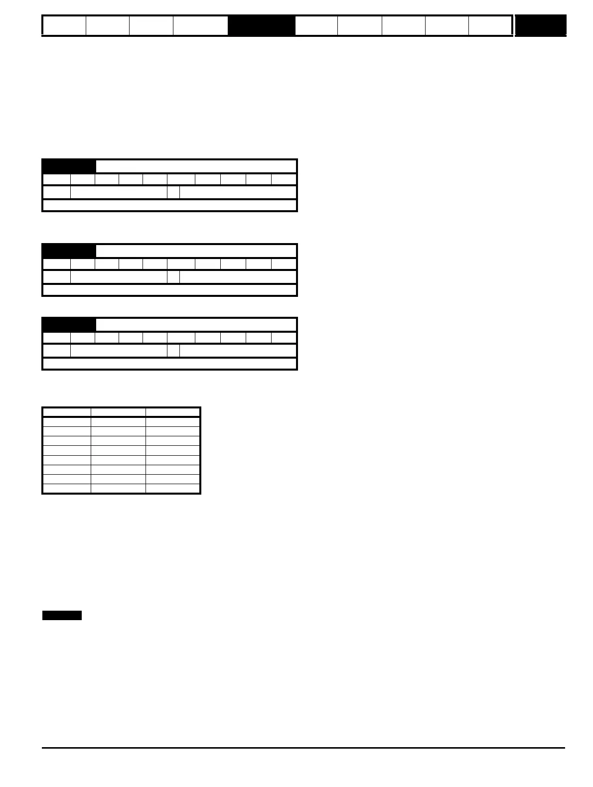
x.14 Encoder comms baud rate
RW Txt US
Ú
0 to 7
Ö
2
Update rate: Background read
Pr value Pr string Baud rate
0 100 100k
1 200 200k
2 300 300k
3 400 400k
4 500 500k
5 1000 1M
6 1500 1.5M
7 2000 2M