Menus 15 to 17
SM-I/O Plus
Parameter
structure
Keypad and
display
Parameter
x.00
Parameter
description format
Advanced parameter
descriptions
Macros
Serial comms
protocol
Electronic
nameplate
Performance RFC mode
292 Unidrive SP Advanced User Guide
www.controltechniques.com Issue Number: 10
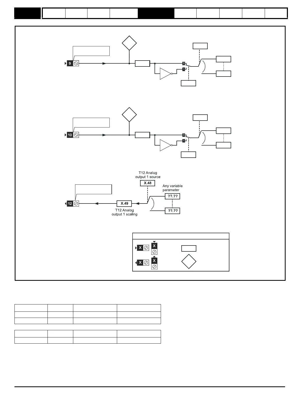
Figure 5-33 SM-I/O Plus Analog Input / Output logic diagram
This module has two analog inputs (AI1 and AI2) and one analog output (AO1). The input operates in voltage mode only and the nominal full scale
level is 9.8V. This ensures that when the input is driven from a voltage produced from the drive's own 10V supply, the input can reach full scale. The
output operates in voltage mode only.
Terminal Input Input modes Resolution
T9 AI1 Voltage only 10 bit plus sign
T10 AI2 Voltage only 10 bit plus sign
Terminal Output Output modes Resolution
T12 AO1 Voltage only 10 bit plus sign
X.41
T9 Analog
input 1
scaling
input 1 invert
X.40
T9 Analog input 1
(RW)
parameter
Read-only (RO)
parameter
Input
terminals
Output
terminals
The parameters are all shown at their default settings
X.45
X.44
T10 Analog
input 2
invert
T9 Analog
input 1
T10 Analog input 2
T10 Analog
input 2
T10 Analog
input 2
destination
T10 Analog
input 2
scaling
T12 Analog
output 1

 Loading...


