Parameter
structure
Keypad and
display
Parameter
x.00
Parameter
description format
Advanced parameter
descriptions
Macros
Serial comms
protocol
Electronic
nameplate
Performance RFC mode
Menu 5
Unidrive SP Advanced User Guide 119
Issue Number: 10 www.controltechniques.com
1. Stationary test
• A stationary test is performed to measure the stator resistance (Pr 5.17)
•Pr 5.17 is saved to EEPROM.
• A stationary test is performed to measure the transient inductance (Pr 5.24). When this test is complete the current loop gains (Pr 4.13 and Pr
4.14) are over-written with the correct values based on the calculations given in Menu 4. A moderately accurate value of ϕ
1
as described in menu
4 can be obtained from the measured stator resistance and transient inductance to set the correct current limits and flux level in the motor.
•Pr 4.13, Pr 4.14 and Pr 5.24 are saved to EEPROM.
2. Rotating test
• The stationary tests are performed and the parameters saved to EEPROM as described above.
• A rotating test is performed in which the motor is accelerated using the ramp rate defined by Pr 2.11 (or Pr 21.04 if motor 2 is selected) to
2
/
3
of
rated frequency and held at this frequency for up to 36 seconds. During the rotating test the stator inductance (Pr 5.25), and the motor saturation
breakpoints (Pr 5.29 and Pr 5.30) are calculated. The power factor is also modified for user information only, and is not used after this point
because the stator inductance will have a non-zero value. When the test is complete the motor coasts to a stop. The motor should be unloaded
for this test to produce correct results.
•Pr 5.25, Pr 5.29 and Pr 5.30 are saved to EEPROM.
3. Inertia measurement
• The drive attempts to accelerate the motor in the forward direction up to
3
/
4
x rated load rpm and then back to standstill. Several attempts may be
made, starting with rated torque/16, and then increasing the torque progressively to x
1
/
8
, x
1
/
4
, x
1
/
2
and x1 rated torque if the motor cannot be
accelerated to the required speed. 5s acceleration time is allowed during the first four attempts and 60s on the final attempt. If the required speed
is not achieved on the final attempt the test is aborted and a tuNE1 trip is initiated. If the test is successful the acceleration and deceleration times
are used to calculate the motor and load inertia which is written to Pr 3.18. (If closed-loop vector control without position feedback is used the first
attempt is made with x
1
/
4
because the torque control at very low speeds is not as accurate as when position feedback is used. Using a higher
level of torque ensures that the motor starts).
•Pr 3.18 is saved to EEPROM.
The calculated value of inertia is dependant on the value of the motor torque per amp parameter (Pr 5.32) which is calculated by the drive using an
efficiency of 0.9. Therefore the inertia may be inaccurate if the motor efficiency is substantially different from 0.9. However, if the inertia is used for
automatic speed loop gain set up the calculated gains will not be affected because Kt is also used in these calculations and any inaccuracy cancels
out.
The test algorithm attempts to remove the effect of any load on the motor other than the torque required to accelerate and decelerate the motor, i.e.
friction and windage losses, static torque load etc. Provided the average torque during acceleration and the average torque during deceleration are
the same the effect of the additional torque is removed and the inertia value is calculated correctly.
4. Current controller gain calculation only
• No current is applied to the motor.
• The current loop gains are calculated based on the value of the motor inductance (Pr 5.24) and resistance (Pr 5.17) and written to Pr 4.13 and
Pr 4.14.
•Pr 4.13 and Pr 4.14 are saved to EEPROM.
This is intended to be used as a method of setting up the current loop gains from user defined values of motor inductance and resistance. The drive
should not be enabled to perform these calculations. If the parameter is set to 4 it is automatically cleared by the drive once the calculation is
complete. It should be noted that the value changes back to zero within a few hundred milliseconds of being set to 4 by the user.
Servo
In this mode the following parameters are used in the vector control algorithm.
All these parameters can be set by the user. The motor set-up is constantly recalculated in the background task, therefore modifying these
parameters even after auto-tune will affect the performance of the drive. The auto-tune test can be used to overwrite the user or default settings as
described below. It should be noted that the current loop gains (Pr 4.13 and Pr 4.14) are not updated as part of any test if either the stator resistance
or the transient inductance for the active motor map are zero.
1: Short low speed test
• The motor is rotated by 2 electrical revolutions (i.e. up to 2 mechanical revolutions) in the forward direction. The drive applies rated current to the
motor during the test and measures the encoder phase angle (Pr 3.25) only. The phase angle measurement is taken when the motor has stopped
at the end of the test, therefore there must be no load on the motor when it is at rest for the correct angle to be measured. This test takes
approximately 2 seconds to complete and can only be used where the rotor settles to a stable position in a short time.
•Pr 3.25 is saved to EEPROM.
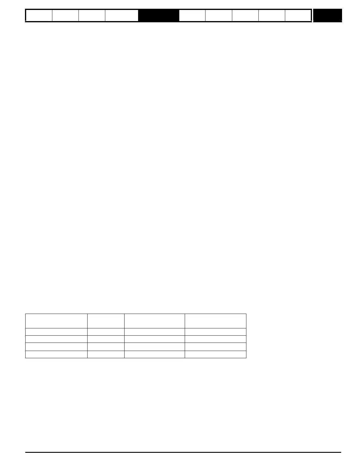
Parameter
Required for good
performance
Required for excellent
performance
Encoder phase angle Pr 3.25 99
No. of poles Pr 5.11 99
Transient inductance (σL
s
)
Pr 5.24 9
Stator resistance (Rs) Pr 5.17 9

 Loading...


