Menu 10
Parameter
structure
Keypad and
display
Parameter
x.00
Parameter
description format
Advanced parameter
descriptions
Macros
Serial comms
protocol
Electronic
nameplate
Performance RFC mode
198 Unidrive SP Advanced User Guide
www.controltechniques.com Issue Number: 10
For SP0xxx, SP1xxx and SP2xxx drives the default value is a suitable value for standard braking resistors that can be mounted within the drive
heatsink as given in the table below. For larger drives the default is 0.00.
This parameter defines the time period that the braking resistor installed can stand full braking volts without damage. The setting of this parameter is
used in determining the braking overload time.
This parameter defines the time between periods when the braking IGBT is on for the full power braking time so that the average power in the resistor
does not exceed the rating of the resistor.
For SP0xxx, SP1xxx and SP2xxx drives the default value is a suitable value for standard braking resistors that can be mounted within the drive as
given in the table below.
If Pr 10.31 is set to zero then the braking resistor thermal protection system is disabled.
Drive voltage rating
Parameter default
SP0xxx SP1xxx and SP2xxx All other sizes
200V 0.06s 0.09s 0.00s
400V 0.01s 0.02s 0.00s
575V and 690V N/A N/A 0.00s
Drive voltage rating Full braking volts
200V 390V
400V 780V
575V 930V
690V 1120V
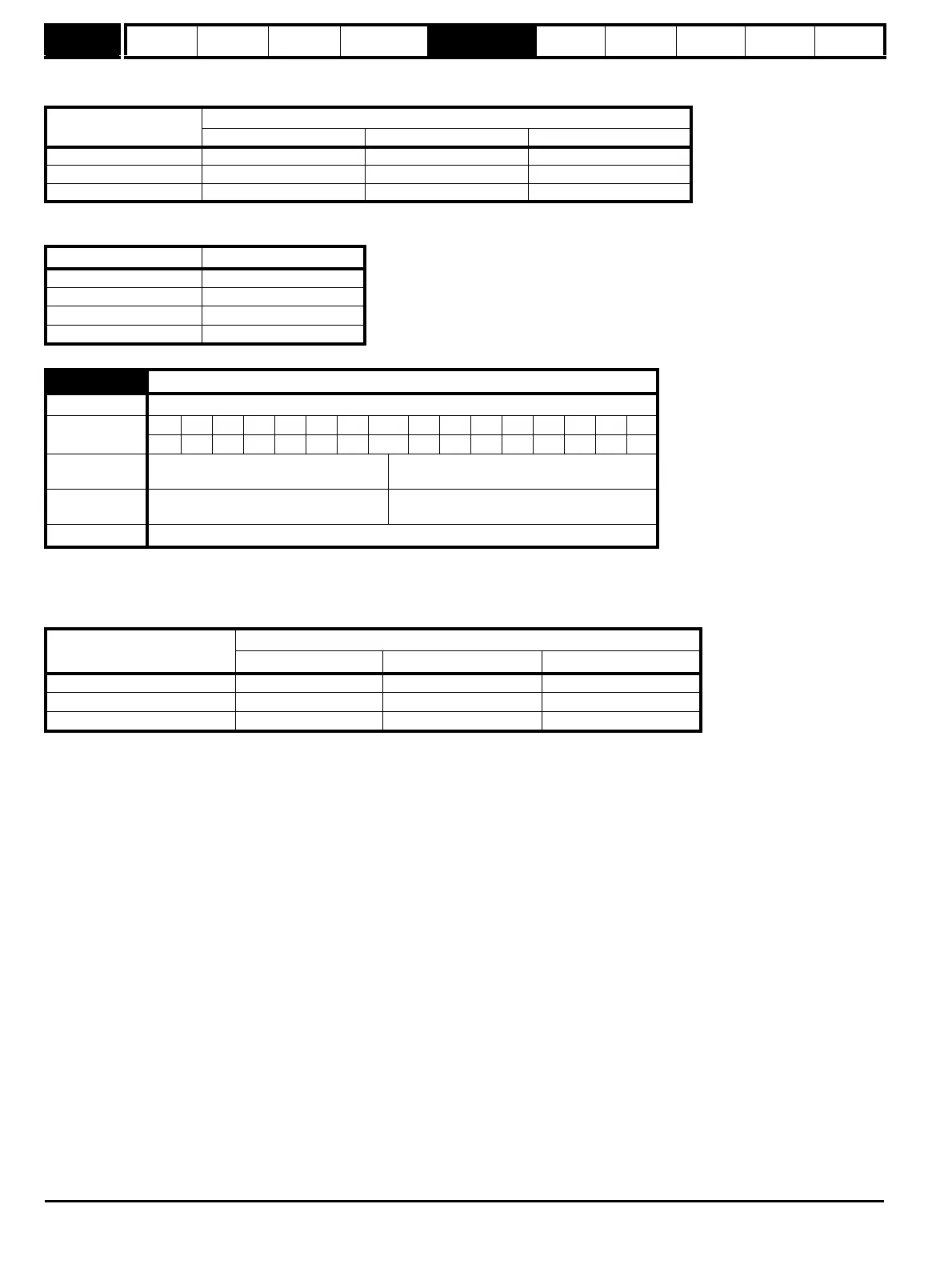
10.31 Full power braking period
Drive modes Open-loop, Closed-loop vector, Servo, Regen
Coding
Bit SP FI DE Txt VM DP ND RA NC NV PT US RW BU PS
1 111
Range
Open-loop, Closed-loop vector, Servo,
Regen
0.0 to 1500.0 s
Default
Open-loop, Closed-loop vector, Servo,
Regen
See below
Update rate Background read
Drive voltage rating
Parameter default
SP0xxx SP1xxx, SP2xxx All other sizes
200V 2.6s 3.3s 0.00s
400V 1.7s 3.3s 0.00s
575V and 690V N/A N/A 0.00s

 Loading...


