Menus 15 to 17
SM-I/O 32
Parameter
structure
Keypad and
display
Parameter
x.00
Parameter
description format
Advanced parameter
descriptions
Macros
Serial comms
protocol
Electronic
nameplate
Performance RFC mode
326 Unidrive SP Advanced User Guide
www.controltechniques.com Issue Number: 10
The drive parameter defined by this parameter is the write register for the fast update method. Each bit in the write register will control the
corresponding I/O line provided it has been set up as an output in the direction register parameter. If this parameter is set to 0.00 or a non existent
parameter then all I/O lines set up as outputs are held in the non-active state. The write register parameter range may not be large enough to allow all
I/O lines to be controlled. The value written to the write register is subject to the normal range limiting.
Worked Example
By storing 20.21 in Pr x.43, Pr 20.21 will become the direction register for the digital I/O lines on the SM-IO 32 module. Storing 20.22 in Pr x.47 will
make Pr 20.22 the read register. Storing 20.23 in Pr x.48 will make Pr 20.23 the write register.
Storing a value of 29 (11101 in binary) in Pr 20.21 will make digital I/O lines 1, 3, 4 and 5 (which corresponds to bit 0, 2, 3 and 4) as digital output bits
and the remaining I/O lines will remain as digital input. Now these digital outputs can be written to using the write register Pr 20.23. Storing a value of
23 (10111 in binary) in Pr 20.23 will set digital I/O 1, 3 and 5 high (ON) and digital I/O 4 low (OFF). The write register will have no effect on digital I/O
2 when it tries to set it high (ON) because this digital I/O line has not been set as a digital output line by direction register. The read register, Pr 20.22
will show a value of 21 (binary 10101).
The control of the 32 digital I/O is limited by the range of the controlling parameter. Control of all the 32 digital I/O lines can only be achieved using
software like SyPTLite and SyPTPro. For example, with Pr 18.13 as the write register, 16 digital outputs can be written and with Pr 20.23 as the write
register, all the 32 digital outputs can be written
The error status is provided so that only one option error trip is required for each Solutions Module slot. If an error occurs, the reason for the error is
written to this parameter and the drive may produce an ‘SLX.Er’ trip (where X is the slot number). A value of zero indicates that the Solutions Module
has not detected an error, a non-zero value indicates that an error has been detected. (See Table 5-33 on page 323 for the meaning of the values in
this parameter). When the drive is reset, this parameter is cleared for the relevant Solutions Module.
This Solutions Module includes a temperature monitoring circuit. If the PCB temperature exceeds 85°C (185°F), the drive fan is forced to operate at
full speed (for a minimum of 10s). If the temperature falls below 75°C (167°F), the fan can operate normally again. If the PCB temperature exceeds
90°C (194°F), the drive will trip and the error status is set to 74.
The Solutions Module includes a processor with software. The software version is displayed in Pr x.02 and Pr x.51 in the form Pr x.02 = xx.yy and
Pr x.51 = zz, where:
xx specifies a change that affects hardware compatibility
yy specifies a change that affects product documentation
zz specifies a change that does not affect the product documentation.
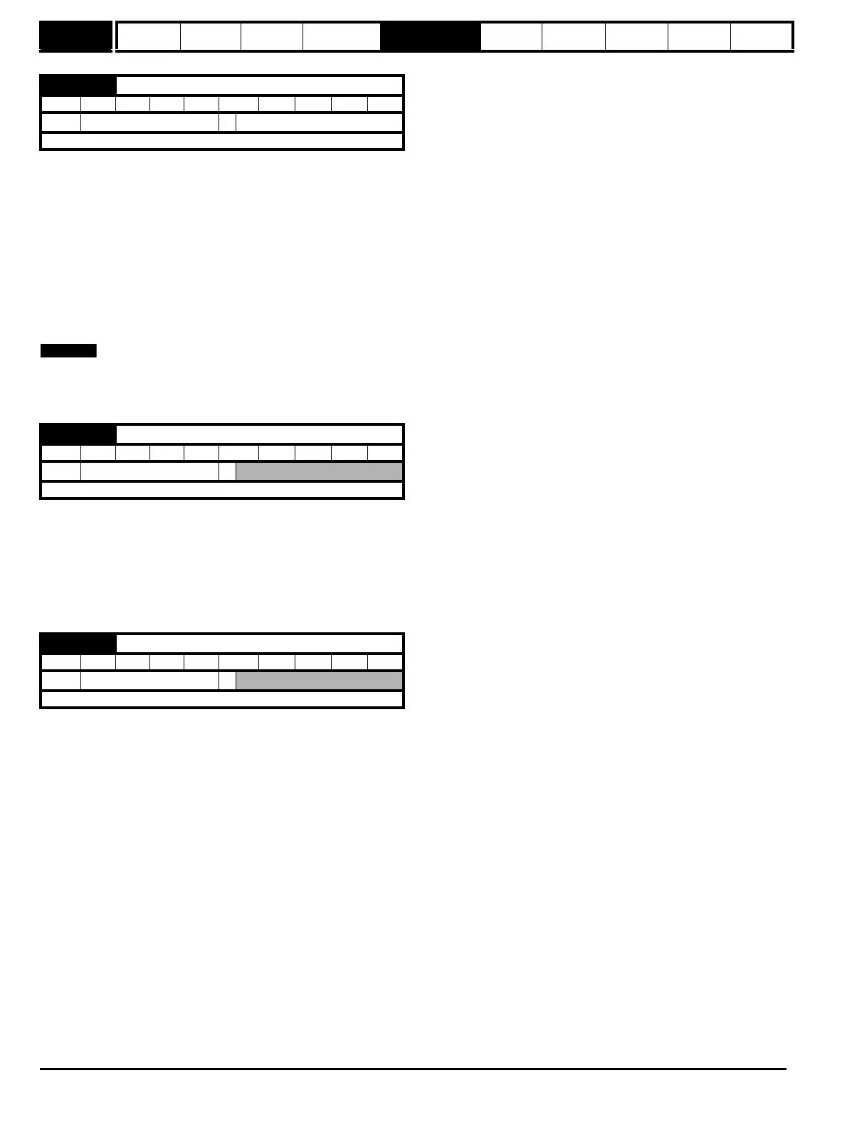
x.48 Fast update method write register
RW Uni PT US
Ú
Pr 0.00 to Pr 21.51
Ö
Pr 0.00
Update rate: Read on drive reset
x.50 Solutions Module error status
RO Uni NC PT
Ú
0 to 255
Ö
Update rate: Background write
x.51 Solutions Module software sub-version
RO Uni NC PT
Ú
0 to 99
Ö
Update rate: Write on power-up

 Loading...


