Menus 15 to 17
SM-I/O Plus
Parameter
structure
Keypad and
display
Parameter
x.00
Parameter
description format
Advanced parameter
descriptions
Macros
Serial comms
protocol
Electronic
nameplate
Performance RFC mode
290 Unidrive SP Advanced User Guide
www.controltechniques.com Issue Number: 10
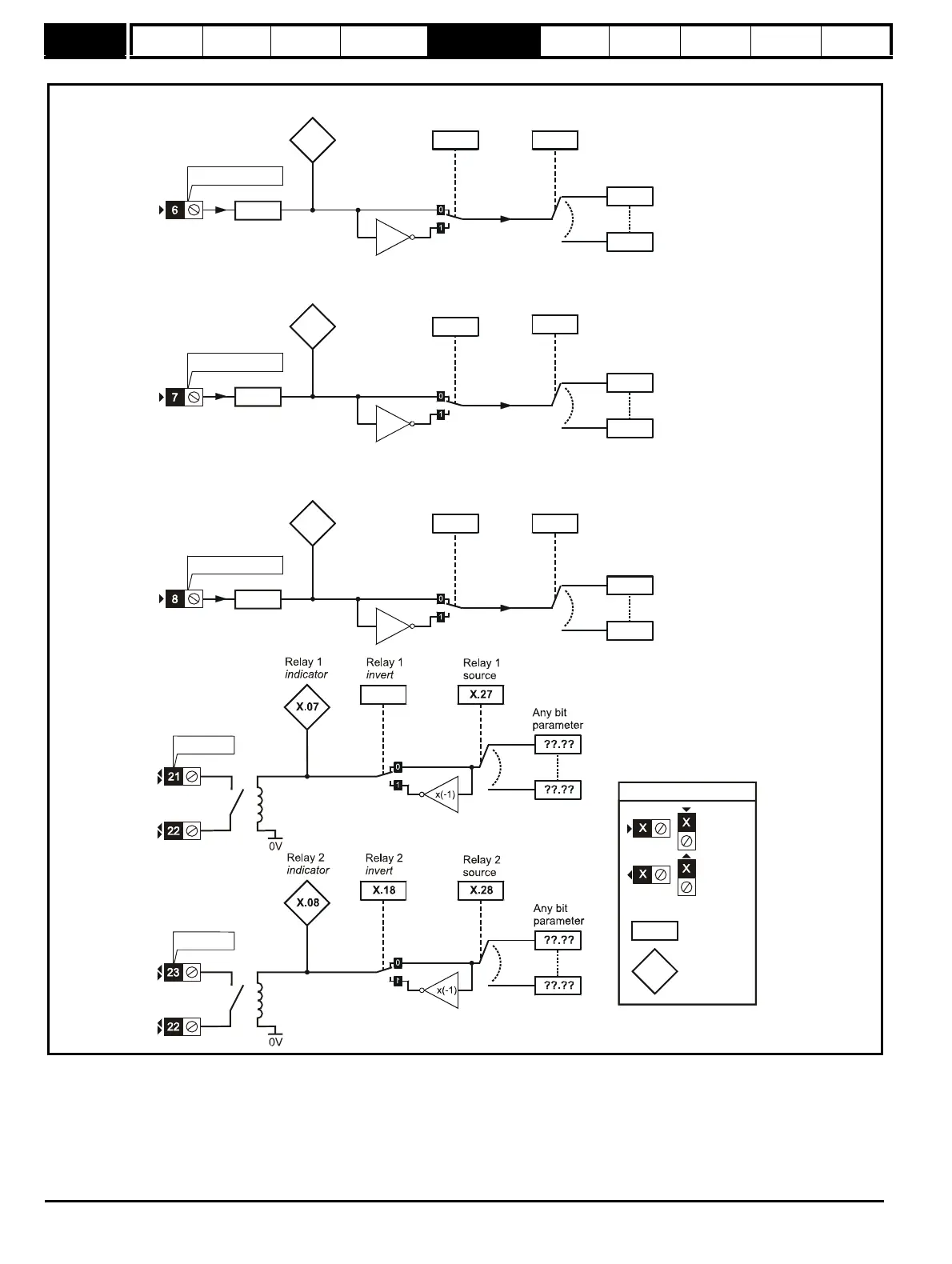
Figure 5-32 SM I/O Plus Digital Input/Output logic diagram 2
This module has three digital input/outputs (DI/O1 to DI/O3), three digital inputs (DI4 to DI6) and two relays outputs (D07 and DO8). The inputs can
operate with positive or negative logic (defined by Pr x.29), the outputs operate with positive logic using high side drivers only and the relay outputs
operate with positive logic only.
X.24
x(-1)
X.14
T6 digital input 4
state indicator
X.04
X.25
x(-1)
X.16X.06
The parameters are all shown
at their default setting
(RW)
parameter
Read-only
(RO)
parameter
Input
terminals
Output
terminals
destination
T7 digital input 5
state
indicator
T7 digital
input 5
invert
destination
T8 digital input 6
state
indicator
T8 digital
input 6
invert
destination
X.29
Positive
logic select
X.29
Positive
logic select
X.29
Positive
logic select

 Loading...


