Menu 7
Parameter
structure
Keypad and
display
Parameter
x.00
Parameter
description format
Advanced parameter
descriptions
Macros
Serial comms
protocol
Electronic
nameplate
Performance RFC mode
150 Unidrive SP Advanced User Guide
www.controltechniques.com Issue Number: 10
5.9 Menu 7: Analog I/O
Hardware
The drive has three analog inputs (AI1 to AI3) and two analog outputs (AO1 and AO2). Each input has a similar parameter structure and each output
has a similar parameter structure. The nominal full scale level for inputs in voltage mode is 9.8V. This ensures that when the input is driven from a
voltage produced from the drive's own 10V supply, the input can reach full scale.
Update rate
The analog inputs are sampled every 4ms except where the destinations shown in the table below are chosen, the input is in voltage mode and other
conditions necessary for short cutting are met.
It should be noted that the analog inputs are always sampled every 4ms in Open-loop mode. However, the window filter applied to analog input 1 (see
Pr 7.26) can be set to a time that is shorter than 4ms. There is no advantage in doing this, as it simply reduces the resolution of the input data, which
is still only sampled and routed to its destination parameter every 4ms.
Analog outputs are updated every 4ms except when one of the following is the source and high speed update mode is selected. In high speed mode
the output operates in voltage mode, is updated every 250μs, special scaling is used as described in the table and the user scaling is ignored.
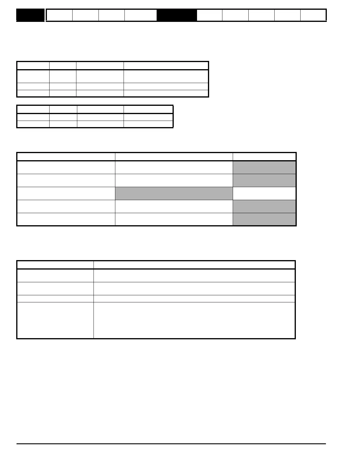
Terminal Input Input modes Resolution
5/6 AI1 Voltage only
12 bit plus sign
(16 bit plus sign as a speed reference)
7 AI2 0 to 6 10 bit plus sign
8 AI3 0 to 9 10 bit plus sign
Terminal Output Output modes Resolution
9 AO1 0 to 3 10 bit plus sign
10 AO2 0 to 3 10 bit plus sign
Input destination Closed-loop vector or Servo mode sample rate Regen mode sample rate
Pr 1.36 - Analog reference
250μs
(AI1 subject to window filter. See Pr 7.26 on page 159)
Pr 1.37 - Analog reference
250μs
(AI1 subject to window filter. See Pr 7.26 on page 159)
Pr 3.10 - Power feed forward compensation
AI1 - 4ms
AI2 or 3 - 1ms
Pr 3.22 - Hard speed reference
250μs
(AI1 subject to window filter. See Pr 7.26 on page 159)
Pr 4.08 - Torque reference
AI1 – 4ms
AI2 or 3 – 250μs
Output source Scaling
Pr 3.02 – speed
(Closed-loop vector and servo modes only)
10.0V = SPEED_MAX
Pr 4.02 - torque prod current
10.0V = Kc / 0.45
where Kc is the current scaling factor for the drive
Pr 4.17 - magnetising current 10.0V = Kc / 0.45
Pr 5.03 - output power
(Closed-loop vector and servo modes only)
The output is the product of the active current and the voltage component in phase with the
active current (vsy x isy).
10V would be produced when:
Active current = Kc / 0.45
Peak phase voltage in phase with the active current = DC_VOLTAGE_MAX / 2
 Loading...


