Menu 3
All modes
Parameter
structure
Keypad and
display
Parameter
x.00
Parameter
description format
Advanced parameter
descriptions
Macros
Serial comms
protocol
Electronic
nameplate
Performance RFC mode
70 Unidrive SP Advanced User Guide
www.controltechniques.com Issue Number: 10
Ab, Fd, Fr, Ab.Servo, Fd.Servo, Fr.Servo, SC
Pr 3.35 defines the marker mode. If this parameter is zero the marker system operates in a conventional manner, but if this parameter is non-zero the
marker causes a full position reset.
SC.Hiper, SC.EnDat, SC.SSI and 03.39 = 1 or 2 (Rotary encoder)
Pr 3.35 must be set to the number of comms bits used to represent one revolution of the encoder. The single turn comms resolution may be higher
than the resolution of the sine waves per revolution.
SC.Hiper, SC.EnDat, SC.SSI and 03.39 = 0 (Linear encoder)
Pr 3.35 must be set up to the total number of bits representing the whole encoder position in the comms message. This parameter is not used with
linear SC.Hiper encoders as the number of bits used to represent the whole position is always 32.
EnDat, SSI
Pr 3.35 must be set to the number of bits used to represent one revolution of the encoder.
Although Pr 3.35 can be set to any value from 0 to 32, if the value is less than 1, the resolution is 1 bit. Some SSI encoders (SC.SSI or SSI) include a
power supply monitor alarm using the least significant bit of the position. It is possible for the drive to monitor this bit and produce an Enc6 trip if the
power supply is too low (see Pr 3.40). If the encoder gives this information the comms resolution should be set up to include this bit whether it is being
monitored by the drive or not. It should be noted that some SSI encoders include trailing zeros after the position. This parameter should be set up to
include the trailing zero bits.
It is possible for the drive to set up this parameter automatically from information obtained from the encoder via Hiperface or EnDat interfaces (see
Pr 3.41).
The encoder supply voltage present on the drive encoder connector is defined by this parameter as 0 (5V), 1 (8V), or 2 (15V).
This parameter defines the baud rate for the encoder comms when using SSI or EnDat encoders. However, a fixed baud rate of 9600 baud is used
with HIPERFACE encoders and this parameter has no effect.
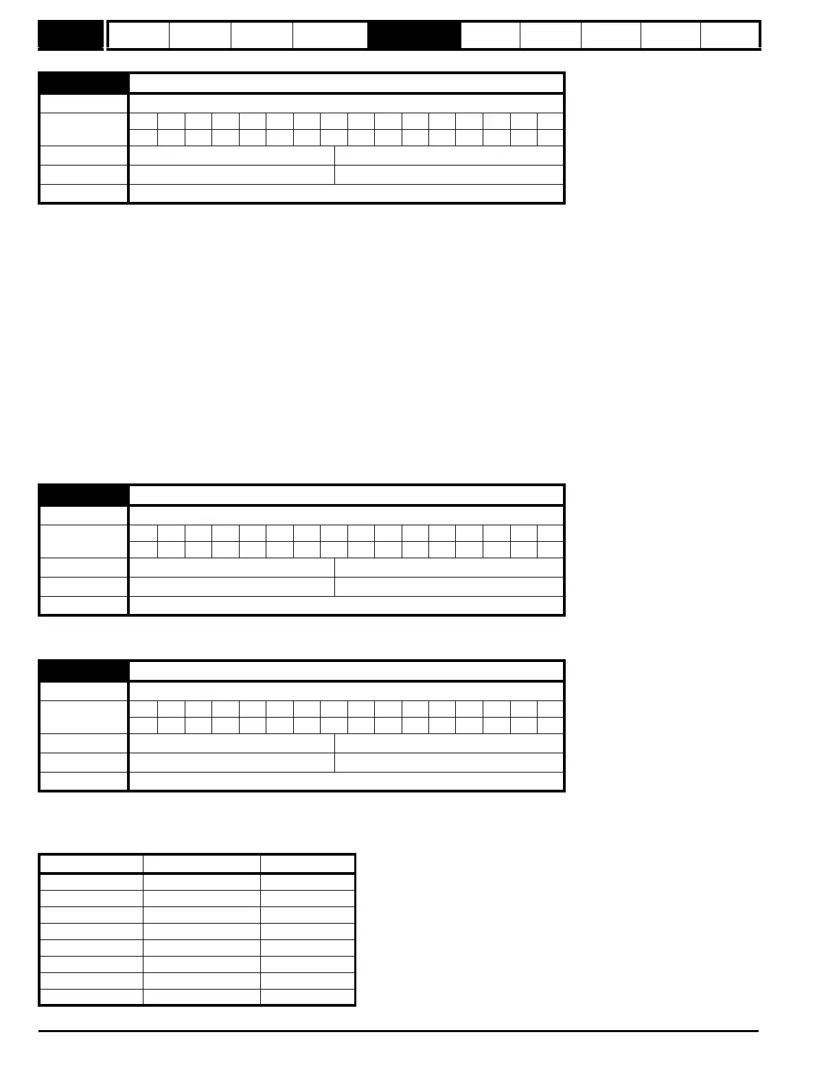
3.35
Drive encoder single turn comms bits / Linear encoder comms bits/Marker mode
Drive modes Open-loop, Closed-loop vector, Servo
Coding
Bit SP FI DE Txt VM DP ND RA NC NV PT US RW BU PS
111
Range Open-loop, Closed-loop vector, Servo 0 to 32 bits
Default Open-loop, Closed-loop vector, Servo 0
Update rate Background read (Only has any effect when the drive is disabled)
3.36
Drive encoder supply voltage
Drive modes Open-loop, Closed-loop vector, Servo
Coding
Bit SP FI DE Txt VM DP ND RA NC NV PT US RW BU PS
1 111
Range Open-loop, Closed-loop vector, Servo 0 to 2
Default Open-loop, Closed-loop vector, Servo 0
Update rate Background read
3.37
Drive encoder comms baud rate
Drive modes Open-loop, Closed-loop vector, Servo
Coding
Bit SP FI DE Txt VM DP ND RA NC NV PT US RW BU PS
1 111
Range Open-loop, Closed-loop vector, Servo 0 to 7
Default Open-loop, Closed-loop vector, Servo 2
Update rate Background read (Only has any effect when the drive is disabled)
Parameter value Parameter string Baud rate
0 100 100k
1 200 200k
2 300 300k
3 400 400k
4 500 500k
5 1000 1M
6 1500 1.5M
7 2000 2M

 Loading...


