Parameter
structure
Keypad and
display
Parameter
x.00
Parameter
description format
Advanced parameter
descriptions
Macros
Serial comms
protocol
Electronic
nameplate
Performance RFC mode
Menu 3
All modes
Unidrive SP Advanced User Guide 71
Issue Number: 10 www.controltechniques.com
Any baud rate can be used when encoder comms is used with a SINCOS encoder to obtain the absolute position during initialization. When encoder
comms is used alone(EnDat or SSI selected with Pr 3.38) the time taken to obtain the comms position must be 160μs or less, otherwise the drive
initiates an Enc4 trip.
There is a delay obtaining the position from an encoder using comms alone. The length of this delay affects the sample rate and timing of the position
used by the drive for control and the position passed to Solutions Modules. If for an EnDat encoder the position within one turn can be obtained in
30μs and the whole comms message including CRC can be obtained in 60μs then fast sampling is used, otherwise slow sampling is used as shown
below. If for an SSI encoder the whole position can be obtained in 30μs fast sampling is used. In each case the position is sampled within the encoder
at the start of the comms message from the drive.
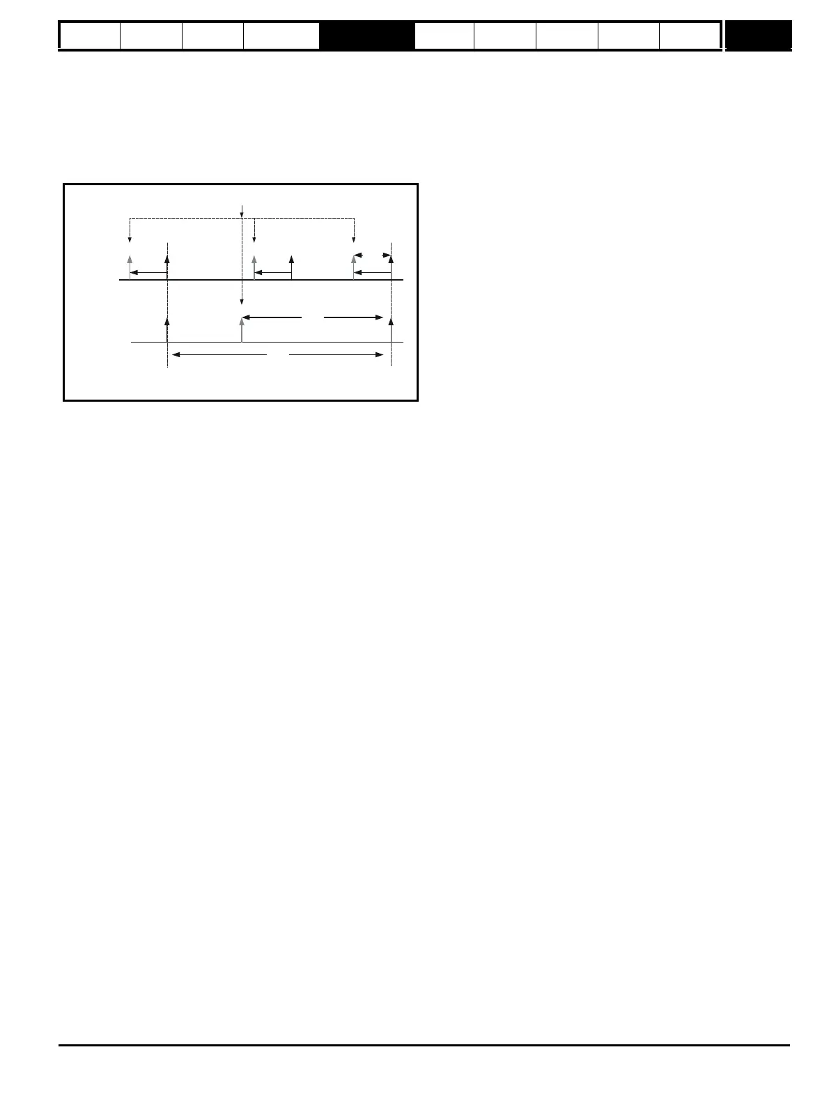
In the example the current/torque sampling rate is 4kHz, but this will change if a different switching frequency is selected. If fast sampling is used the
control position used to define the drive reference frame is obtained every current/torque control sample and the position passed to Solutions
Modules is obtained 20μs before the datum point where other types of encoders are sampled. If slow sampling is used both the control position and
the position passed to Solutions Modules is obtained 150μs before the datum. When fast sampling is used the delay introduced into the control
system by the encoder is less, and so a higher control system bandwidth will be possible. So that the position values from the encoder can be used in
a position control system compensation is provided for the delay in obtaining the position before it is made available to Solutions Modules or in the
drive position parameters so that it appears to have been sampled at the datum. This compensation is based on the delay (i.e. 20μs or 150μs) and
the change of position over the previous sample.
EnDat comms
The following equations are used by the drive to determine the time taken to obtain the position information from an EnDat encoder. These are based
on t
cal
≤ 5μs, where t
cal
is the time from the first clock edge of the position command message from the drive to the first clock edge when the encoder
responds as defined in the EnDat specification. This limit of 5μs may exclude a small number of EnDat encoders from being used by the drive as a
comms only feedback device. It is also assumed that t
D
≤ 1.25μs where t
D
is the data delay from the encoder as defined by the EnDat specification for
105m of cable. Although with higher clock rates shorter cables must be used, and t
D
will be less than 1.25μs, the calculation performed by the drive
always assumes t
D
=1.25μs. It should be noted that all values are rounded up to the nearest microsecond.
Command message time = t
command
= 10T or t
cal
whichever is the longest
Where: T = 1/Baud Rate, t
cal
= 5μs
Time for single turn position = t
command
+ t
D
+ (2 + Single turn resolution) x T
= t
command
+ t
D
+ (2 + Pr 3.35) x T
Where: t
D
= 1.25μs
Time for whole message including CRC = Time for single turn position + (Number of turns bits + 5) x T
= Time for single turn position + (Pr 3.33 + 5) x T
For example an encoder with 12 turns bits, 13 bit single turn resolution and a baud rate of 2M would give the following times:
Time for single turn position = 14μs (13.75μs rounded up)
Time for the whole message including CRC = 23μs (22.25μs rounded up)
A recovery time (tm) is specified for EnDat encoders, that is the time required between the end of one data transfer and the beginning of the next one.
If this time is not allowed between messages that transfer the position from the encoder, the encoder operates in continuous mode and the data from
the encoder will be incorrect and cause CRC errors. tm is nominally 20μs, but may vary from 10μs to 30μs (EnDat 2.1 specification). If tm is greater
than 23μs and 6 or 12kHz switching is used, which have a fast sample rate of 83μs, it is possible for the time allowed for tm to be too short. Therefore
if 6 or 12kHz switching are used the total message transfer time should not exceed 53μs unless tm can be guaranteed to be less than 30μs by a
suitable margin.
Slow
Sampling
Fast
Sampling
250 s
μ
Datum
Point
Datum
Point
150 s
μ
20 s
μ
Start of comms messages and encoder position sampling point

 Loading...


