Parameter
structure
Keypad and
display
Parameter
x.00
Parameter
description format
Advanced parameter
descriptions
Macros
Serial comms
protocol
Electronic
nameplate
Performance RFC mode
Menu 3
Closed-loop
Unidrive SP Advanced User Guide 63
Issue Number: 10 www.controltechniques.com
0: user set-up
With the default value the user should enter the required speed controller gains.
1: Bandwidth set-up
If bandwidth based set-up is required the following parameters must be set correctly: Pr 3.20 = required bandwidth, Pr 3.21 = required damping factor,
Pr 3.18 = motor + load inertia (it is possible to measure the load inertia as part of the auto-tuning process, see Pr 5.12 on page 117), Pr 5.32 = motor
torque per amp.
Ki = J / (Kc x Kt) x (2π x Bandwidth / Kbw)
2
= Pr 3.18 / (Kc x Pr 5.32) x (2π x Pr 3.20 / Kbw)
2
Where: Kbw = √[ (2ξ
2
+ 1) +√((2ξ
2
+ 1)
2
+ 1) ]
Kp = 2 ξ √ [(Ki x J) / (Kc x Kt)] = 2 ξ √ [(Pr 3.11 x Pr 3.18) / (Kc x Pr 5.32)]
2: Compliance angle set-up
If compliance angle based set-up is required the following parameters must be set correctly: Pr 3.19 = required compliance angle, Pr 3.21 = required
damping factor, Pr 3.18 = motor + load inertia (it is possible to measure the load inertia as part of the auto-tuning process, see Pr 5.12 on page 117),
Pr 5.32 = motor torque per amp.
Ki = 1 / Compliance angle (rad s
-1
)
Kp = 2 ξ √ [(Ki x J) / (Kc x Kt)] = 2 ξ √ [(Pr 3.11 x Pr 3.18) / (Kc x Pr 5.32)]
3: Kp gain times 16
If this parameter is set to 3 the Kp gain (from whichever source) is multiplied by 16. This is intended to boost the range of Kp for applications with very
high inertia. It should be noted that if high values of Kp are used it is likely that the speed controller output will need to be filtered (see Pr 4.12) or the
speed feedback will need to be filtered (see Pr 3.42). If the feedback is not filtered it is possible the output of the speed controller will be a square
wave that changes between the current limits causing the integral term saturation system to malfunction.
The motor and load inertia represents the total inertia driven by the motor. This is used to set the speed controller gains (see Pr 3.13 on page 60) and
to provide torque feed-forwards during acceleration when required. (see Pr 4.11 on page 100) (It is possible to measure the inertia as part of the auto-
tune process, see Pr 5.12 on page 117.
The compliance angle is the required angular displacement when the drive delivers a torque producing current equivalent to the current scaling (Kc)
with no field weakening.
The bandwidth is defined as the theoretical 3dB point on the closed-loop gain characteristic of the speed controller as a second order system. At this
point the phase shift is approximately 60°. This parameter is used to define the bandwidth used for setting up the speed loop gain parameters
automatically when Pr 3.17 = 1.
3.18
Motor and load inertia
Drive modes Closed-loop vector, Servo
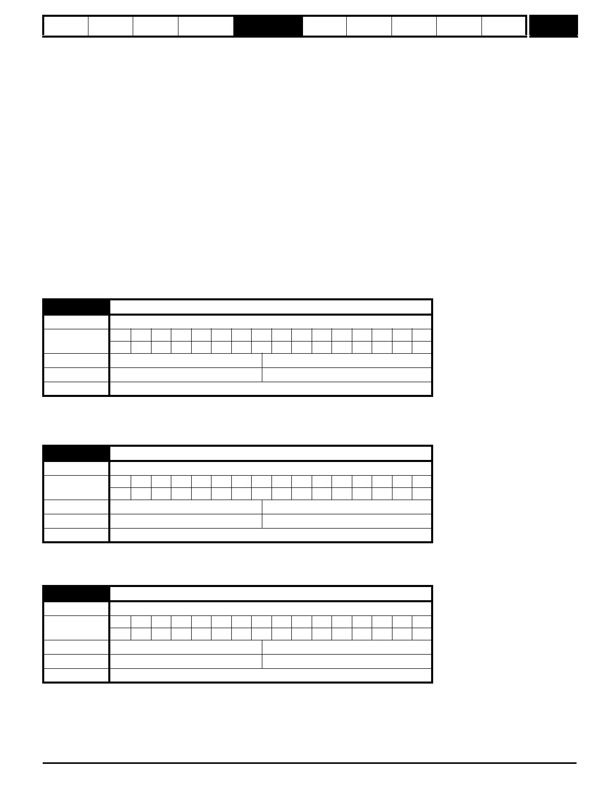
Coding
Bit SP FI DE Txt VM DP ND RA NC NV PT US RW BU PS
5 111
Range Closed-loop vector, Servo
0.00000 to 90.00000 kg m
2
Default Closed-loop vector, Servo 0.00000
Update rate Background (1s) read
3.19
Compliance angle
Drive modes Closed-loop vector, Servo
Coding
Bit SP FI DE Txt VM DP ND RA NC NV PT US RW BU PS
1 111
Range Closed-loop vector, Servo 0.0 to 359.9 °mechanical
Default Closed-loop vector, Servo 4.0
Update rate Background (1s) read
3.20
Bandwidth
Drive modes Closed-loop vector, Servo
Coding
Bit SP FI DE Txt VM DP ND RA NC NV PT US RW BU PS
111
Range Closed-loop vector, Servo 0 to 255 Hz
Default Closed-loop vector, Servo 10 Hz
Update rate Background (1s) read

 Loading...


