Parameter
structure
Keypad and
display
Parameter
x.00
Parameter
description format
Advanced parameter
descriptions
Macros
Serial comms
protocol
Electronic
nameplate
Performance RFC mode
Menus 15 to 17
SM-I/O Lt Tmr
Unidrive SP Advanced User Guide 303
Issue Number: 10 www.controltechniques.com
This parameter can be used to invert the analog input reference (i.e. multiply the input scaling result by -1).
Only parameters that are not protected can be controlled by analog inputs. If a non-valid parameter is programmed to the destination of an analog
input, the input is not routed anywhere. After a modification to this parameter, the destination is only changed when a reset is performed.
The parameter required to be represented as an analog signal by the analog output on Terminal T3 should be programmed in this parameter. Only
parameters that are not protected can be programmed as a source. If a non-valid parameter is programmed as a source, the output will remain at
zero. After a modification to this parameter, the source is only changed when a reset is performed.
This parameter can be used to scale the analog output if so desired. However in most cases it is not necessary as the output is automatically scaled
such that when the source parameter is at its maximum, the analog output will be at its maximum.
The error status is provided so that only one option error trip is required for each Solutions Module slot. If an error occurs, the reason for the error is
written to this parameter and the drive may produce an ‘SLX.Er’ trip (where X is the slot number). A value of zero indicates that the Solutions Module
has not detected an error, a non-zero value indicates that an error has been detected. (See Table 5-17 on page 297 for the meaning of the values in
this parameter for the SM-I/O Lite and SM-I/O Timer). When the drive is reset, this parameter is cleared.
This Solutions Module includes a temperature monitoring circuit. If the PCB temperature exceeds 65°C, the drive fan is forced to operate at full speed
(for a minimum of 20s). If the temperature falls below 65°C, the fan can operate normally again. If the PCB temperature exceeds 70°C, the drive will
trip on SLX.Er, and the error status is set to 74.
The Solutions Module includes a processor with software. The software version is displayed in Pr x.02 and Pr x.51 in the form Pr x.02 = xx.yy and Pr
x.51 = zz.
Where:
xx specifies a change that affects hardware compatibility
yy specifies a change that affects product documentation
zz specifies a change that does not affect the product documentation
When a Solutions Module is installed that does not contain software, both Pr x.02 and Pr x.51 appear as zero.
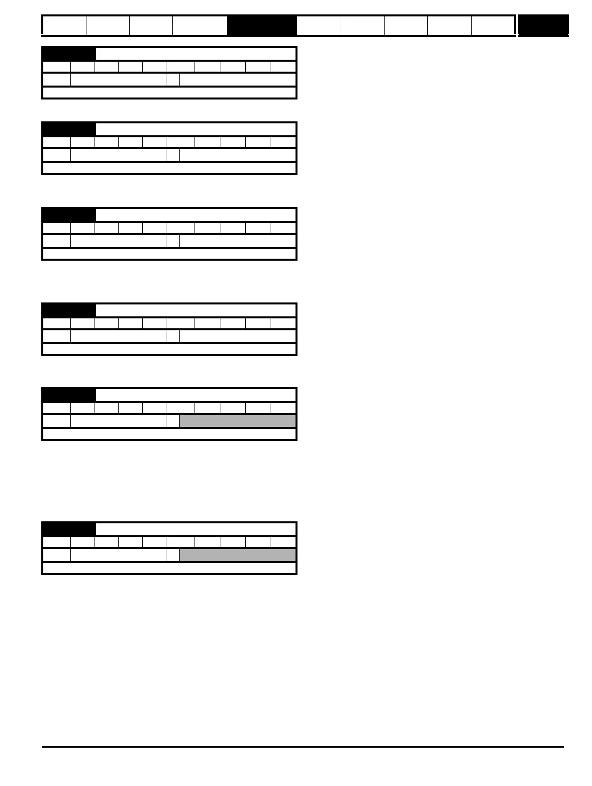
x.42 Analog input 1 invert (Terminal T2)
RW Bit PT US
Ú
OFF(0) or On(1)
Ö
OFF(0)
Update rate: Background read
x.43 Analog input 1 destination (Terminal T2)
RW Uni PT US
Ú
Pr 0.00 to Pr 21.51
Ö
Pr 0.00
Update rate: Read on drive reset
x.48 Analog output 1 source (Terminal T3)
RW Uni PT US
Ú
Pr 0.00 to Pr 21.51
Ö
Pr 0.00
Update rate: Read on drive reset
x.49 Analog output 1 scaling (Terminal T3)
RW Uni US
Ú
0.000 to 4.000
Ö
1.000
Update rate: Background read
x.50 Solutions Module error status
RO Uni NC PT
Ú
0 to 255
Ö
Update rate: Background write
x.51 Solutions Module software sub-version
RO Uni NC PT
Ú
0 to 99
Ö
Update rate: Write on power-up

 Loading...


