Parameter
structure
Keypad and
display
Parameter
x.00
Parameter
description format
Advanced parameter
descriptions
Macros
Serial comms
protocol
Electronic
nameplate
Performance RFC mode
Menu 9
Unidrive SP Advanced User Guide 171
Issue Number: 10 www.controltechniques.com
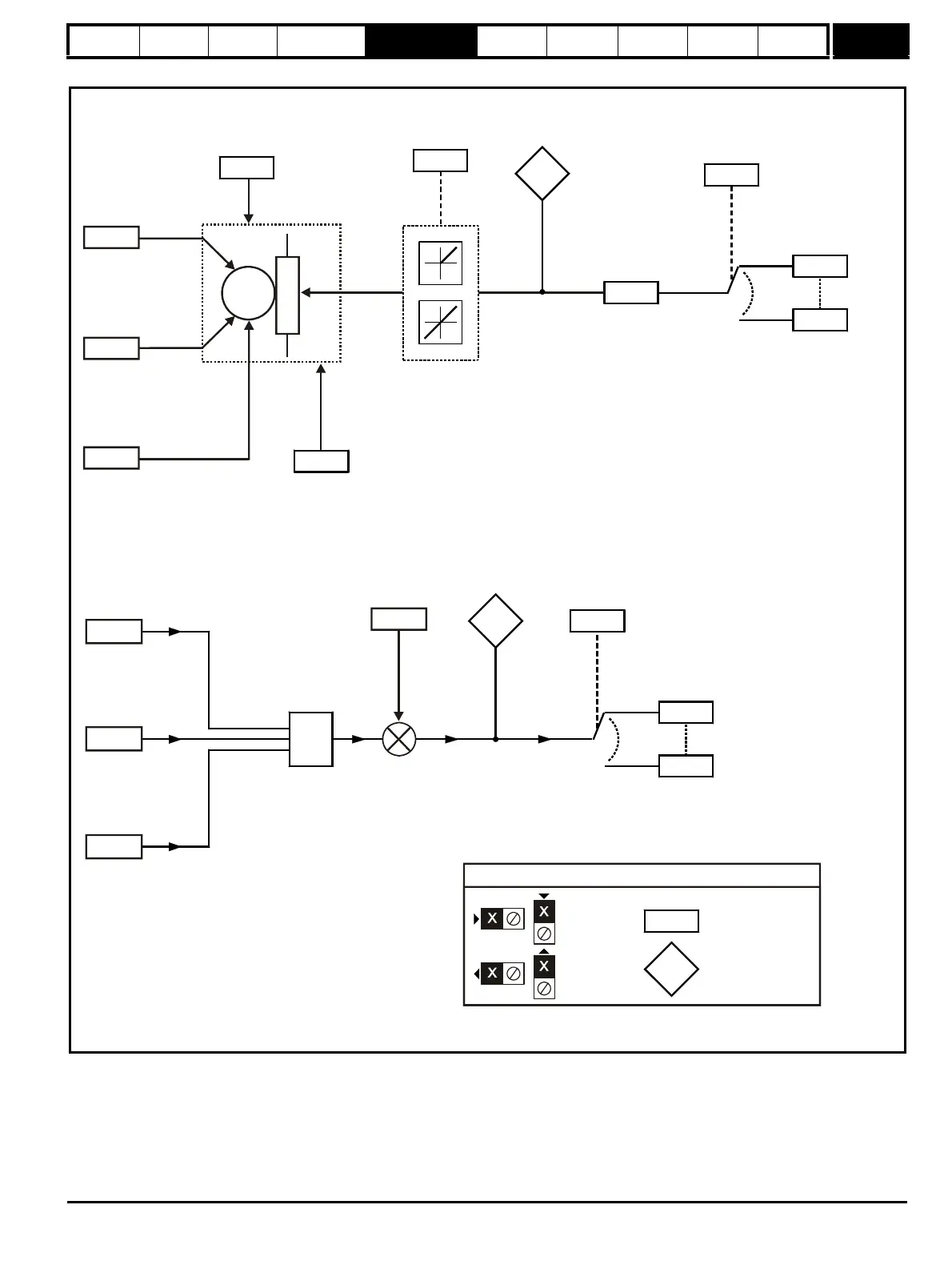
Figure 5-17 Menu 9 logic diagram: Motorized pot and binary sum
Menu 9 contains 2 logic block functions (which can be used to produce any type of 2 input logic gate, with or without a delay), a motorized pot function
and a binary sum block. One menu 9 or one menu 12 function is executed every 4ms. Therefore the sample time of these functions is 4ms x number
of menu 9 and 12 functions active. The logic functions are active if one or both the sources are routed to a valid parameter. The other functions are
active if the output destination is routed to a valid unprotected parameter.
9.30
Binary-sum
logic twos
9.29
Binary-sum
logic ones (LSB)
9.31
Binary-sum
logic fours (MSB)
parameter
9.23
Motorized
pot. rate
9.27
Motorized pot.
down
9.26
Motorized pot.
up
M
9.03
9.22
Motorized
pot. bipolar
select
9.21
9.28
Motorized pot.
reset to zero
Motorized pot.
mode
+
+
(RW)
parameter
Read-only (RO)
parameter
Input
terminals
Output
terminals
The parameters are all shown at their default settings
Function disabled if set
to a non valid destination
Function disabled if set
to a non valid destination

 Loading...


