Parameter
structure
Keypad and
display
Parameter
x.00
Parameter
description format
Advanced parameter
descriptions
Macros
Serial comms
protocol
Electronic
nameplate
Performance RFC mode
Menus 15 to 17
SM-Uni Enc Pl
Unidrive SP Advanced User Guide 267
Issue Number: 10 www.controltechniques.com
The simulated encoder output (incremental), Ab, Ab.L, Fd, Fd.L can be scaled using the above parameter.
The simulated encoder output (incremental), Ab, Ab.L, Fd, Fd.L can be scaled using the above parameter.
An encoder simulation output can be generated from any parameter as a source as defined by Pr x.24 (00.00 disables encoder simulation). Although
any parameter can be used, the source parameter is assumed to be a 16 bit position value in the form of a roll-over counter. Therefore only
parameters with a range of -32768 to 32767 or 0 to 65535 are normally used. The marker is simulated when the source rolls over or under.
The sources update rate should be considered when setting up a simulated encoder output, for example with Pr x.05 as the source this has an
update rate of 250μs (shortcut in software) with Pr x.30 this has an update rate of 4ms (averaging is applied for the simulated encoder output in this
example to prevent “stepping effects” being seen on the simulated encoder output).
When the Solutions Module is connected to a high precision encoder (i.e. SinCos) and the source has been selected as the internal position (Pr x.05),
the resolution can be increase to a 24 bit position value by setting Pr x.27 to a one.
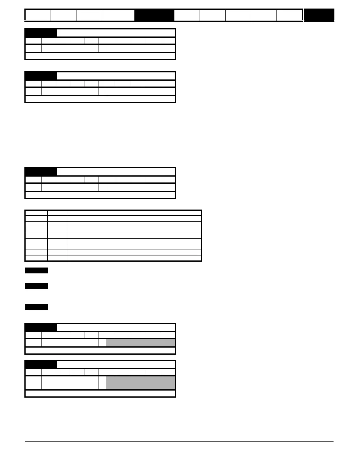
Pr
x.28
defines the output mode for simulated encoder output as follows.
Modes 6 and 7 are only available with the drive software versions 01.07.00 onwards, and issue 4 SM-Universal Encoder Plus.
If the source is not the feedback device, the simulator waits until all feedback devices are initialized before the starting to output. The wait for
initialisation does not occur if the drive software version is less than V01.08.00.
Also refer to the SM-Universal Encoder Plus User Guide for further detailed information.
x.26 Encoder simulation ratio denominator
RW Uni US
Ú
0.0000 to 3.0000
Ö
1.0000
Update rate: Background read
x.27 Encoder simulation resolution select
RW Bit NC US
Ú
OFF (0) or On (1)
Ö
OFF (0)
Update rate: Background read
x.28 Encoder simulation mode
RW Txt US
Ú
0 to 7
Ö
0
Update rate: Background read
Pr x.28 String Mode
0 Ab Quadrature
1 Fd Frequency and direction
2 SSI.Gray SSI output (Gray code)
3 SSI.Bin SSI output (Binary format)
4 Ab.L Quadrature with marker LOCK
5 Fd.L Frequency and direction with marker LOCK
6 H.drv Drive ABZ input signals routed through Hardware
7 H.int Solutions Module ABZ input signals routed through Hardware
x.29 Non-marker reset revolution counter
RO Uni NC PT
Ú
0 to 65535 revolutions
Ö
Update rate: 4ms write
x.30 Non-marker reset position
RO Uni NC PT
Ú
0 to 65535 (1/2
16
ths of a
revolution)
Ö
Update rate: 4ms write

 Loading...


