Menu 12
Parameter
structure
Keypad and
display
Parameter
x.00
Parameter
description format
Advanced parameter
descriptions
Macros
Serial comms
protocol
Electronic
nameplate
Performance RFC mode
224 Unidrive SP Advanced User Guide
www.controltechniques.com Issue Number: 10
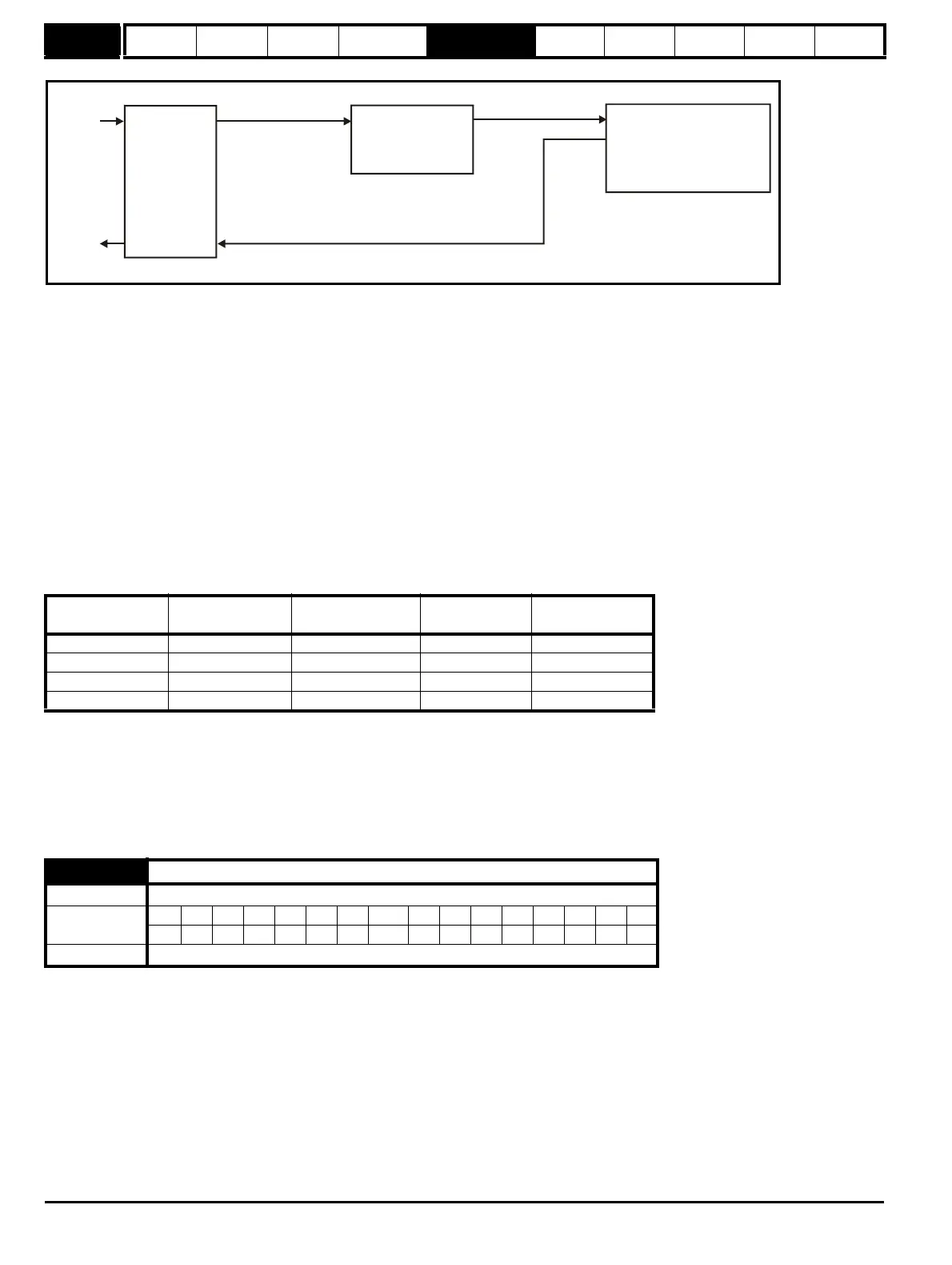
The input reference is provided by the previous drive in the system via the SM-Universal Encoder Plus module and is used as the position source
(Pr 12.08) for the variable selector. The destination of the variable selector is the local position reference for the menu 13 position controller
(Pr 13.21). Pr 13.21 counts up or down based on the delta position from the variable selector and rolls over or under at 65535 or 0. If the controller is
set up to ignore the local reference turns then Pr 13.21 can be used as the position controller reference. If Pr 13.21 is also used as the encoder
simulation source the local reference can also be used to give the reference for the next drive in the system. With this arrangement a ratio is provided
between the input reference and output reference within the variable selector. An addition ratio can be provided within the position controller between
the position in Pr 13.21 and the position reference used by the position controller. The variable selector speed reference can be used to move the
position reference forwards or backwards with respect to the input reference.
11. External Rectifier (SPMC/U) Monitor
This mode is intended to monitor an external rectifier system (SPMC/U) to provide over temperature monitoring, phase loss detection and mains loss
detection. The variable selector inputs should be routed to digital inputs on the drive or a Solutions Module, which are connected to the (SPMC/U)
rectifier status outputs. The external rectifier monitor produces a number of actions depending on the state of the inputs as given in the table below.
The OK/healthy state becomes active immediately both inputs are high, but the other states only become active when the required inputs have been
active for at least 0.5s. The high state is defined as a value greater than or equal to half the source maximum and the low state is defined as a value
less than half the source maximum (with the scaling parameters set to 1.000). If digital inputs are used as the sources and the scaling parameters are
1.000, high is therefore defined as 1, and low is defined as 0. The variable selector output gives 0% if the rectifier is OK/healthy, otherwise it gives
100%. The output should be routed to Pr 6.51 (rectifier not active) so that the drive is not allowed to leave the main loss condition if the rectifier is not
fully phased forwards.
For more information about Oht4.P and PH.P trips, refer to the Unidrive SPM User Guide.
5.14.1 Brake control function
The brake control function can be used to control an electro-mechanical brake via the drive digital I/O. A brake control function is provided for open-
loop operation of induction motors (Open-loop mode) and an alternative brake control function is provided for closed-loop operation of induction
motors or servo motors (Closed-loop vector and Servo modes). The parameters that are common to both brake control functions (Pr 12.40 and
Pr 12.41) are described below. The other parameters used by each of the brake control functions are then described in the section for the appropriate
function.
This parameter should be used as a source for a digital output to control an electro-mechanical brake. This parameter is one to release the brake and
zero to apply the brake. Digital I/O can be automatically configured to use this parameter as a source (see Pr 12.41).
Input 1
(Pr 12.08, Pr 12.28)
Input 2
(Pr 12.09, Pr 12.29)
State Trip
Output
(Pr 12.12, Pr 12.32)
High High Healthy None 0%
High Low Over temperature Oht4.P trip 100%
Low High Phase loss PH.P trip 100%
Low Low Mains Loss None 100%
12.40 Brake release
Drive modes Open-loop, Closed-loop vector, Servo
Coding
Bit SP FI DE Txt VM DP ND RA NC NV PT US RW BU PS
1111
Update rate Background read
Input
reference
Output
reference
SM-Universal
Encoder Plus
module
Source
Pr =Pr
12.08 x.05
mode
Destination
Pr = Pr
12.11 13.21
Menu 13 position controller
Reference source
Pr =Local(4)
Ignore local reference turns
Pr =1
13.04
13.24
Encoder simulation source
Pr = Pr
x.24 13.21

 Loading...


