Parameter
structure
Keypad and
display
Parameter x.00
Parameter
description format
Advanced parameter
descriptions
Macros
Serial comms
protocol
Electronic
nameplate
Performance RFC mode
Unidrive SP Advanced User Guide 23
Issue Number: 10 www.controltechniques.com
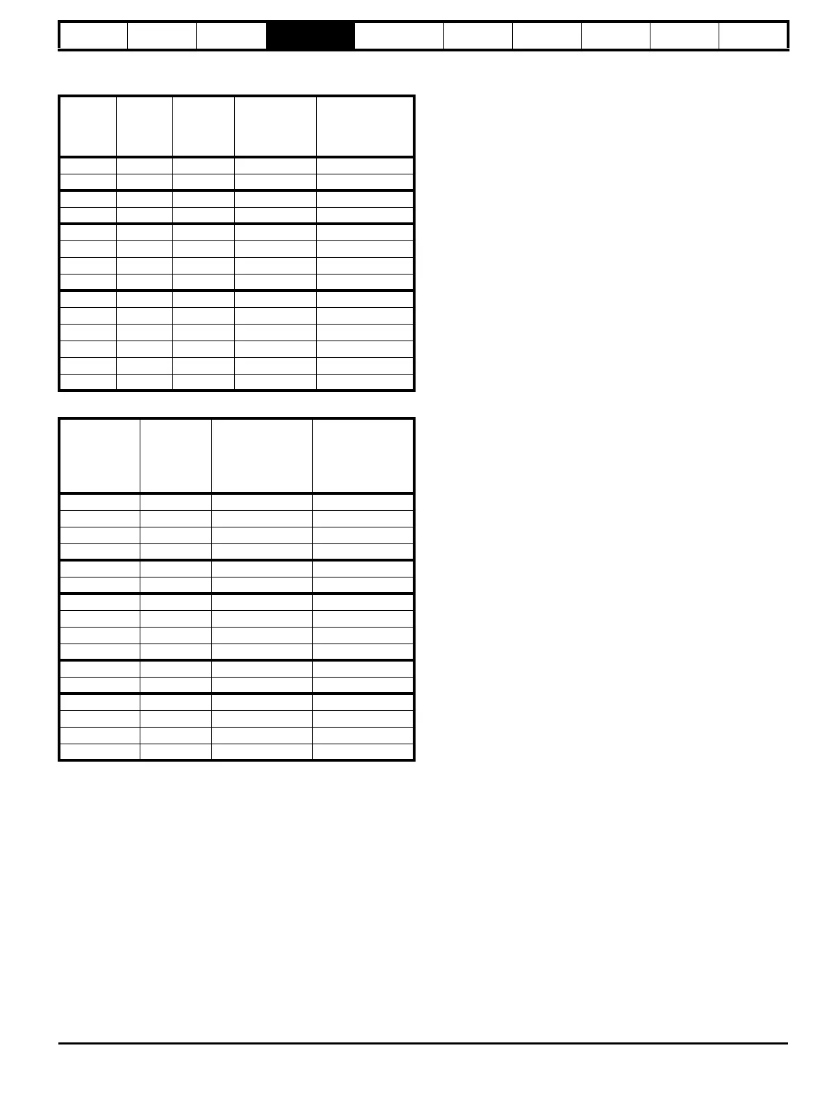
Table 4-3 Maximum motor rated current (sizes 6 to 9 Free
Standing drives)
Table 4-4 Maximum motor rated current (SPM modular drives)
4.1.1 Default
The default values given are the standard drive defaults which are
loaded after a drive reset with 1233 in Pr x.00.
4.1.2 Second motor parameter
Some parameters have an equivalent second motor value that can be
used as an alternative when the second motor is selected with Pr 11.45.
Menu 21 contains all the second motor parameters. In this menu the
parameter specifications include the location of the normal motor
parameter which is being duplicated.
4.1.3 Update rate
Defines the rate at which the parameter data is written by the drive
(write) or read and acted upon by the drive (read). Where background
update rate is specified, the update time depends on the drive processor
load.
Generally the update time is between 2ms and 30ms, however, the
update time is significantly extended when loading defaults, changing
drive mode, transferring data to/from a SMARTCARD, or transferring
blocks of parameters or communications messages to/from the drive
(not a Solutions Module) via the drive serial comms port.
4.2 Sources and destinations
4.2.1 Sources
Some functions have source pointer parameters, i.e. drive outputs, PID
controller etc.. The source pointer parameter range is Pr 0.00 to
Pr 21.51. The source pointer is set up to point to a parameter, which
supplies the information to control the source and this is referred to as
the source data parameter. For example, Pr 7.19 is the source pointer
parameter for analog output 1. If Pr 7.19 is set to a value of 18.11, then
Pr 18.11 is the source data parameter, and as the value of Pr 18.11 is
modified the analog output level is changed.
1. If the parameter number in the source pointer parameter does not
exist the input is taken as zero.
2. If the source is not a bit type source (i.e. not a digital output etc).
then the source level is defined by (source data value x 100%) /
source data parameter maximum. Generally the result is rounded
down to the nearest unit, but other rounding effects may occur
depending on the internal scaling of the particular source function.
3. If the source is a bit, i.e. a digital output, and the source data
parameter is a bit parameter then the input to the source function
follows the value of the source data parameter.
4. If the source is a bit, i.e. a digital output, and the source data
parameter is not a bit parameter the source input is zero if the
source data value is less than source data parameter maximum / 2
rounded down to the nearest unit. The source input is one if the
source data value is greater than or equal to source data parameter
maximum / 2 rounded down to the nearest unit. For example if the
source pointer parameter is set to Pr 18.11, which has a maximum of
32767, the source input is zero if the source data value is less than
16383 and one if it is greater than this.
4.2.2 Destinations
Some functions have destination pointer parameters, i.e. drive inputs,
etc.. The destination pointer parameter range is P 0.00 to Pr 21.51. The
destination pointer parameter is set up to point to a parameter, which
receives information from the function referred to as the destination
parameter.
1. If the parameter number in the destination pointer parameter does
not exist then the output value has no effect.
2. If the destination parameter is protected then the output value has
no effect.
3. If the function output is a bit value (i.e. a digital input) the destination
parameter value does not operate in the same way as a source
described above, but is always either 0 or 1 depending on the state
of the function output whether the destination parameter is a bit
parameter or not.
4. If the function output is not a bit value (i.e. analog input) and the
destination parameter is not a bit parameter, the destination value is
given by (function output x destination parameter maximum) / 100%.
Generally the result is rounded down to the nearest unit, but other
rounding effects may occur depending on the internal scaling of the
particular source function (rounded down to nearest unit). Pr 1.36
and Pr 1.37 are a special case. The scaling shown in the description
of parameter Pr 1.08 is used when any non-bit type quantity is
routed to these parameters.
5. If the function output is not a bit value and the destination parameter
is a bit value, the destination value is 0 if the function output is less
than 50% of its maximum value, otherwise it is 1.
6. If more than one destination selector is routed to the same
destination, the value of the destination parameter is undefined. The
drive checks for this condition where the destinations are defined in
any menu except menus 15 to 17. If a conflict occurs a dESt trip
occurs that cannot be reset until the conflict is resolved.
Model
Kc
A
Pr 11.32
A
Heavy Duty
current rating
A
Normal
Duty current
rating
A
SP6411 154.2 180 180 205
SP6412 180 210 210 236
SP7411 205.7 246 238 290
SP7412 248.5 290 290 350
SP8411 293 342 335 389
SP8412 342 399 389 450
SP8413 391 467.4 450 545
SP8414 472 551 620 545
SP9410 513 598.5 593 690
SP9411 585 684 620 690
SP9412 586 701.1 690 790
SP9413 684 798 790 900
SP9414 782 934.8 900 1010
SP9415 944 1102 1010 1164
Model
Kc
A
Maximum Heavy
Duty
current rating
(Pr 11.32)
A
Maximum Normal
Duty current
rating
A
SPMD1201 133.7 156 192
SPMD1202 164.5 192 248
SPMD1203 214.2 250 312
SPMD1204 248.5 290 350
SPMA1401 154.2 180 205
SPMA1402 180.0 210 236
SPMD1401 154.2 180 205
SPMD1402 180.0 210 246
SPMD1403 205.7 246 290
SPMD1404 248.5 290 350
SPMA1601 85.7 100 125
SPMA1602 107.1 125 144
SPMD1601 85.7 100 125
SPMD1602 107.1 125 144
SPMD1603 123.4 144 168
SPMD1604 144.0 168 192

 Loading...


