Parameter
structure
Keypad and
display
Parameter
x.00
Parameter
description format
Advanced parameter
descriptions
Macros
Serial comms
protocol
Electronic
nameplate
Performance RFC mode
Menu 10
Unidrive SP Advanced User Guide 199
Issue Number: 10 www.controltechniques.com
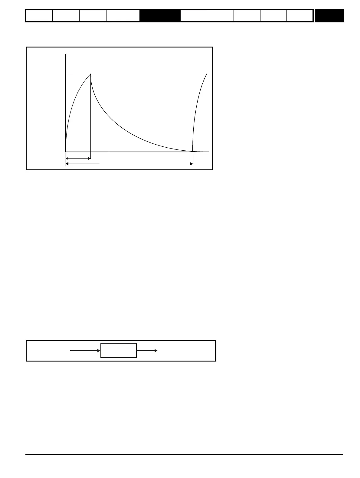
The braking resistor temperature is modelled by the drive as shown below. The temperature rises in proportion to the power flowing into the resistor
and falls in proportion to the difference between the resistor temperature and ambient. Under the conditions shown the resistor is heating up just to
100% of its rated temperature during each braking period.
Assuming that the full power braking time is much shorter than the full power braking period i.e. Pr 10.30 < Pr 10.31 /10 (which is normally the case)
the values for Pr 10.30 and Pr 10.31 can be calculated as follows:
Power flowing into the resistor when the braking IGBT is on, P
on
= Full braking volts
2
/ R
Where:
Full braking volts is defined in the table and R is the resistance of the braking resistor.
Full power braking time (Pr 10.30), T
on
= E / P
on
Where:
E is the total energy that can be absorbed by the resistor when its initial temperature is ambient temperature.
Therefore full power braking time (Pr 10.30), T
on
= E x R / Full braking volts
2
If the average power rating of the resistor is not to be exceeded in the cycle shown in the diagram above, the average power in the resistor is given by
P
av
= P
on
x T
on
/ Tp
Where:
Tp is the full power braking period
P
on
= E / T
on
Therefore P
av
= E / Tp
Therefore full power braking period (Pr 10.31), Tp = E / P
av
The resistance of the braking resistor R, the total energy E and the average power P
av
can normally be obtained for the resistor and used to calculate
Pr 10.30 and Pr 10.31.
If the profile of the power flowing from the motor is know then the instantaneous temperature can be calculated at any point by simulating the braking
resistor with the model shown below.
The temperature of the resistor is monitored by the braking energy accumulator (Pr 10.39). When this parameter reaches 100% the drive will trip if bit
1 of Pr 10.37 is 0, or will disable the braking IGBT until the accumulator falls below 95% if bit 1 Pr 10.37 is 1. The second option is intended for
applications with parallel connected d.c. buses where there are several braking resistors, each of which cannot withstand full d.c. bus voltage
continuously. The braking load will probably not be shared equally between the resistors because of voltage measurement tolerances within the
individual drives. However, once a resistor reaches its maximum temperature its load will be reduced, and be taken up by another resistor.
0
100
%
t
Pr
10.30
Pr
10.31
Overload
accumulator
Pr
10.39
100%
Pav
x (1-e )
-t/Tp
Power from motor
Braking energy overload
accumulator Pr
10.39

 Loading...


