Parameter
structure
Keypad and
display
Parameter
x.00
Parameter
description format
Advanced parameter
descriptions
Macros
Serial comms
protocol
Electronic
nameplate
Performance RFC mode
Menu 5
Unidrive SP Advanced User Guide 121
Issue Number: 10 www.controltechniques.com
The current controllers are used to perform this test, however, the default gains may be too high. It is not possible to carry out the necessary test to
set up the current controllers before the phasing angle is known. If the gains are too high the minimal movement phasing test may cause an OI.AC
trip. If this happens the current controller gains should be reduced progressively until the test is successful. Once the phasing angle is known, the
stationary test to set up the current controller gains only (Pr 5.12 = 4) may be used to obtain the correct gain values for the current controllers.
6. Current controller gain calculation only
• No current is applied to the motor.
• The current loop gains are calculated based on the value of the motor inductance (Pr 5.24) and resistance (Pr 5.17) and written to Pr 4.13 and
Pr 4.14.
•Pr 4.13 and Pr 4.14 are saved to EEPROM.
This is intended to be used as a method of setting up the current loop gains from user defined values of motor inductance and resistance. The drive
should not be enabled to perform these calculations. If the parameter is set to 6 it is automatically cleared by the drive once the calculation is
complete. It should be noted that the value changes back to zero within a few hundred milliseconds of being set to 6 by the user.
Open-loop, Closed-loop vector and Servo
The auto-tune tests may be aborted by removing the run command or the enable or if a trip occurs. During the auto-tune tests the following trips can
occur in addition to the other drive trips.
*The rS trip is produced if the drive cannot achieve the necessary current levels to measure the stator resistance during the test (i.e. there is no motor
connected to the drive), or if the necessary current level can be achieved, but the calculated resistance exceeds the maximum values for the
particular drive size or it exceeds the maximum of Pr 5.17. The maximum measurable value for a particular drive size can be calculated from the
following formula.
Rs
max
= DC_VOLTAGE_MAX x 0.45 / (Kc x √
2
)
where Kc is the current scaling factor for the drive
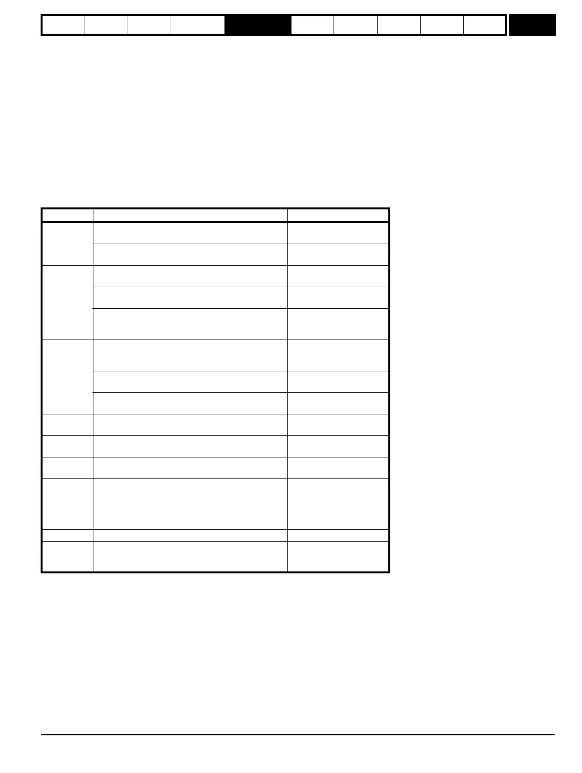
Trip code Reason Test which can cause trip
tunE1
The position feedback did not change
(i.e. motor did not turn or feedback failed)
Closed-loop vector 2
Servo 1,2,5
The motor did not reach the required speed
Closed-loop vector 3
Servo 3
tunE2
Position feedback direction incorrect
Closed-loop vector 2
Servo 1,2
The motor could not be stopped
Closed-loop vector 3
Servo 3
Minimal movement phasing test failed Servo 5
tunE3
Drive encoder commutation signals connected
incorrectly, i.e. direction incorrect.
(Drive encoder only).
Servo 1,2
The motor was moving when the minimal movement
phasing test was initiated
Servo 5
The calculated inertia is out of range
Closed-loop vector 3
Servo 3
tunE4
Drive encoder U commutation signal fail
(Drive encoder only).
Servo 1,2
tunE5
Drive encoder V commutation signal fail
(Drive encoder only).
Servo 1,2
tunE6
Drive encoder W commutation signal fail
(Drive encoder only).
Servo 1,2
tunE7
Motor poles or encoder lines set up incorrectly.A trip is
initiated if the speed is not within ±6.25% of the
expected no load speed just after the motor has
ramped up to speed. This trip will not occur if the motor
poles are set to more than 12.
Closed-loop vector 2
Servo 1,2
tunE Auto-tune stopped before completion All
rS* Stator resistance too high
Open-loop 1, 2
Closed-loop vector 1
Servo 2

 Loading...


