16 – 2
Section 16 • Service Options
MicroVission Controller • Operation and Service Manual • Emerson • 35391MV 1.3
Compressor Start
Activates the output assigned to the compressor motor
starter. The output is connected to terminal X2-4 and is
the 8th LED on the Multi-IO Board.
Remote Ready
Activates the output assigned to the remote ready. The
output is connected to terminal X3-1 and is the 9th LED
on the Multi-IO Board.
Digital Aux Out #1:
Activates the output assigned to the Digital Auxiliary
Output 1. The output is connected to terminal X1-1 and
LED on Digital Auxiliary-IO Board.
Digital Aux Out #2:
Activates the output assigned to the Digital Auxiliary
Output 2. The output is connected to terminal X1-2 and
LED on Digital Auxiliary-IO Board.
Digital Aux Out #3:
Activates the output assigned to the Digital Auxiliary
Output 3. The output is connected to terminal X1-3 and
LED on Digital Auxiliary-IO Board.
Digital Aux Out #4:
Activates the output assigned to the Digital Auxiliary
Output 4. The output is connected to terminal X1-4 and
LED on Digital Auxiliary-IO Board.
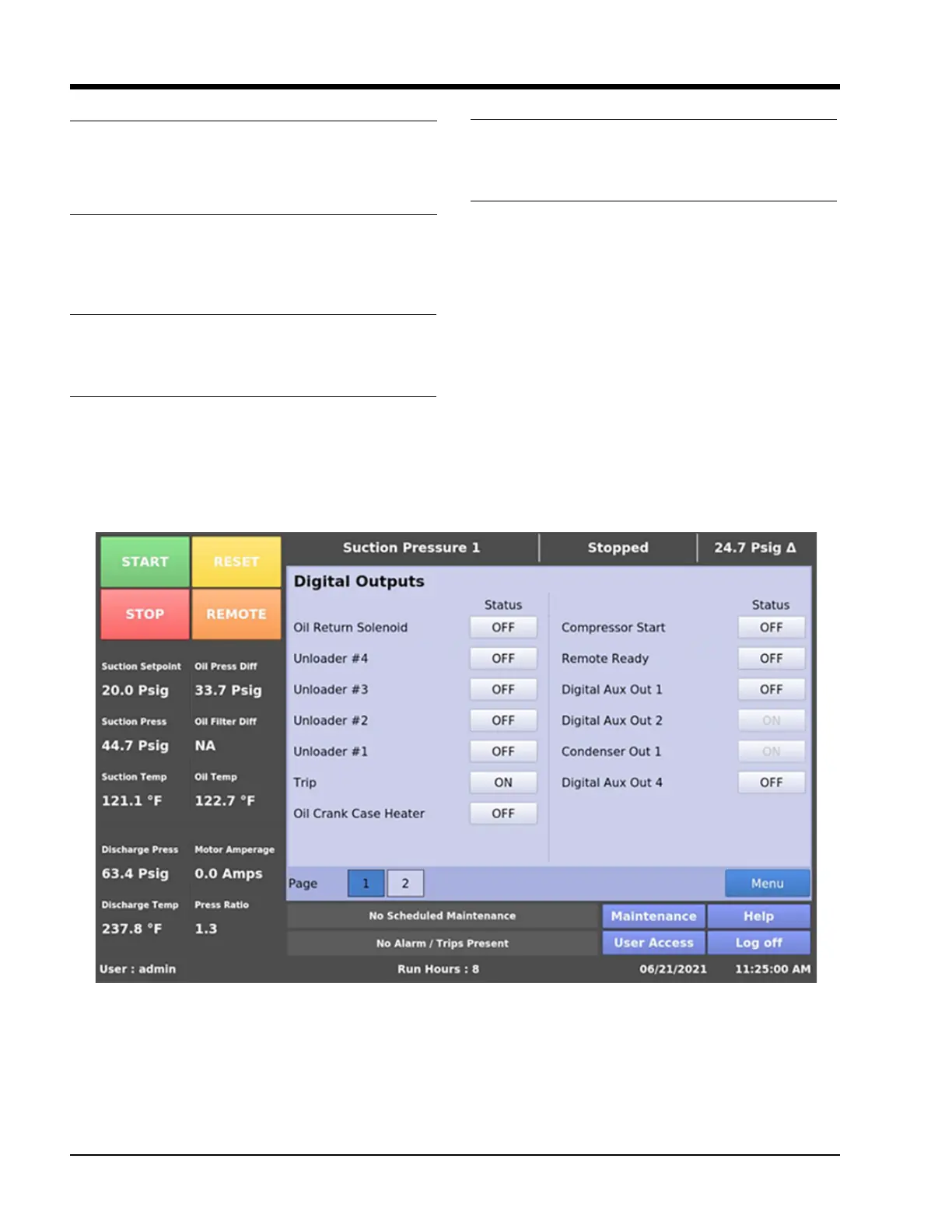
NOTE
The Auxiliary Digital Outputs which are occupied by
other services (like Condenser Control, Auxiliary IO
screen) with run always option would be disabled in
Service Options Screen Page 1, see Figure 16-2.
Figure 16-2. Service Options Screen Page 1 – Occupied Digital Outputs Disabled