16 – 3
Section 16 • Service Options
MicroVission Controller • Operation and Service Manual • Emerson • 35391MV 1.3
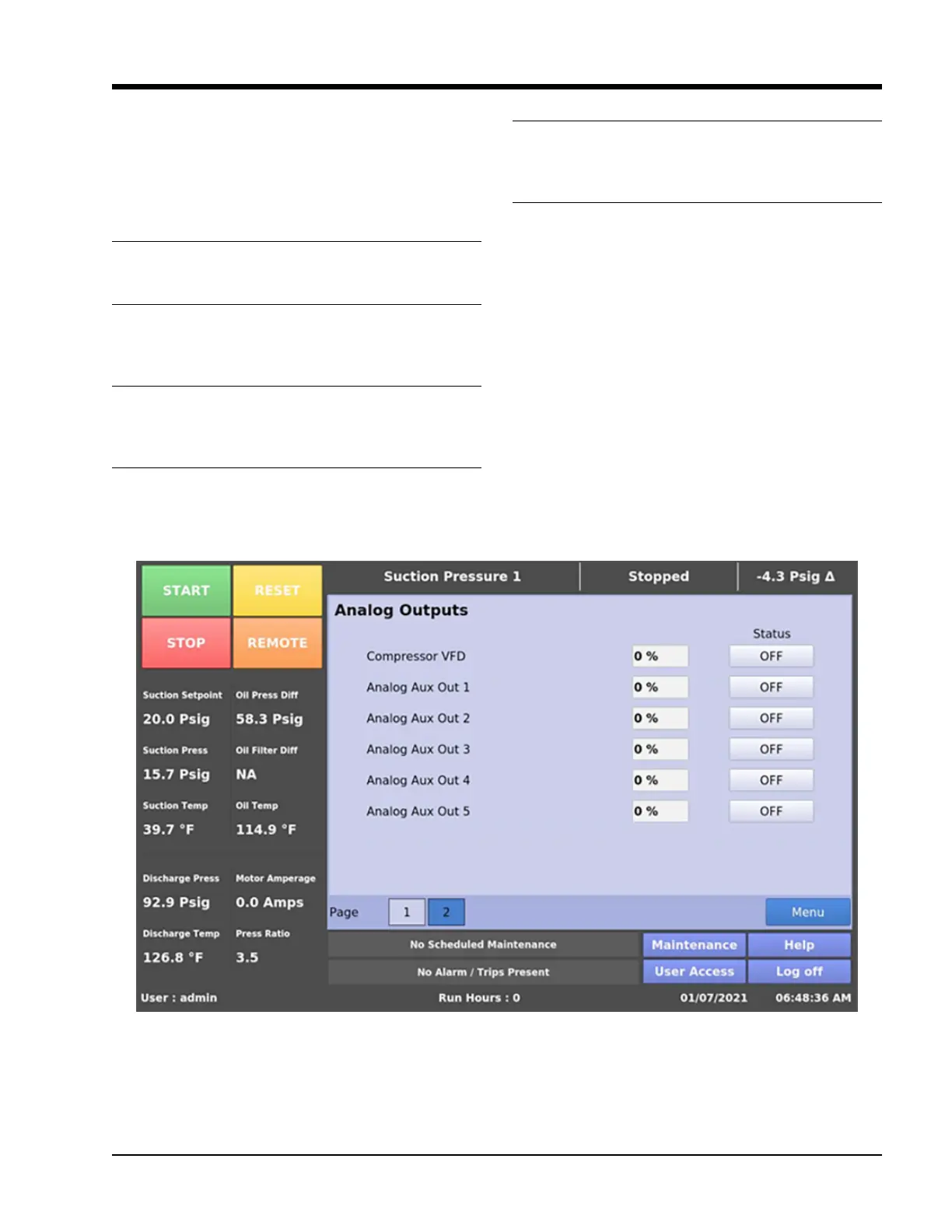
Analog Outputs
The Analog Output (AO) selections allow the operator
to enter a desired value of the output then turn ON the
output, see Figure 16-3. The operator will have to mea-
sure the output using a meter capable of measuring a
4-20mA signal.
Compressor VFD
Sets the analog output assigned to the Compressor VFD.
The output is connected to X12-1 on Multi-IO Board.
Analog Aux Out #1:
Sets the analog output assigned to the Analog Auxiliary
Output 1. The output is connected to X12-3 on Multi-IO
Board.
Analog Aux Out #2:
Sets the analog output assigned to the Analog Auxiliary
Output 2. The output is connected to X12-5 on Multi-IO
Board.
Analog Aux Out #3:
Sets the analog output assigned to the Analog Auxiliary
Output 3. The output is connected to X13-1 on Multi-IO
Board.
Analog Aux Out #4:
Sets the analog output assigned to the Analog Auxiliary
Output 4. The output is connected to X13-3 on Multi-IO
Board.
Analog Aux Out #5:
Sets the analog output assigned to the Analog Auxiliary
Output 5. The output is connected to X13-5 on Multi-IO
Board.
NOTE
The Auxiliary Analog Outputs which are occupied by
other services (like Condenser Control, Auxiliary IO
screen) with run always option would be disabled in
Service Options Screen Page 2, see Figure 16-4.
Figure 16-3. Service Options Screen Page 2 – Analog Outputs