6 – 16
Section 6 • Alarms and Trips
MicroVission Controller • Operation and Service Manual • Emerson • 35391MV 1.3
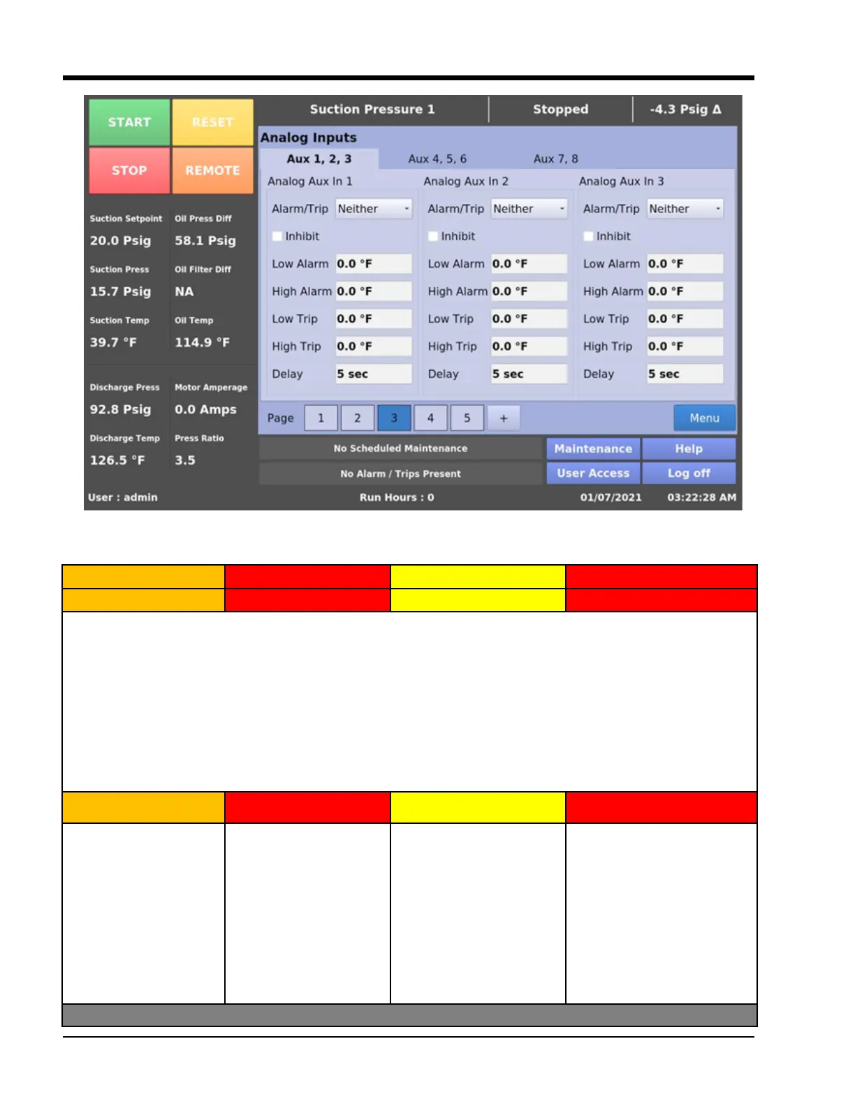
Figure 6-5. Analog Inputs (Auxiliary I/O Screen)
Warnings Inhibits Alarms Trips
Not Running (Idle) Pre-Start Running Running
Analog Aux In 1:
Below messages will be displayed when Analog Aux In 1 satisfy safety conditions.
Warnings are displayed in IDLE condition and it is monitored under Inhibit Checkbox (Refer Figure 6-5)
When “Neither” is selected in Alarm/Trip then No Alarm and Trip for Analog Aux In 1 is monitored.
Alarm condition occurs if the value of a parameter drops below or rises above the congured Alarm setpoint for a
continuous delay time (default 5 seconds).
Trip condition occurs if the value of a parameter drops below or rises above the congured Trip setpoint for a con-
tinuous delay time (default 5 seconds).
Analog Aux In 1 Warning Analog Aux In 1 Inhibit Analog Aux In 1 Alarm Analog Aux In 1 Trip
Inhibit Checked and
Analog Aux In 1 <= Low
Alarm
Inhibit Checked and
Analog Aux In 1 >= High
Alarm
Inhibit Checked and
Analog Aux In 1 <= Low
Alarm
Inhibit Checked and
Analog Aux In 1 >= High
Alarm
“Only Alarm” and Analog
Aux In 1 <= Low Alarm
“Only Alarm” and Analog
Aux In 1 >= High Alarm
“Both” and Analog Aux In 1
<= Low Alarm
“Both” and Analog Aux In 1
>= High Alarm
“Only Trip” and Analog Aux In
1 <= Low Trip
“Only Trip” and Analog Aux In
1 >= High Alarm
“Both” and Analog Aux In 1
<= Low Trip
“Both” and Analog Aux In 1
>= High Trip