2 – 7
Section 2 • Hardware Architecture
MicroVission Controller • Operation and Service Manual • Emerson • 35391MV 1.3
Digital In-Out Board I/O
For information about each Digital I/O signal, see Table
2-4. Auxiliary Digital I/O.
Auxiliary Digital Output #1 - #4
• Optional digital outputs that can be congured in
user dened manner. When Condenser Control is se-
lected in Conguration Screen, these outputs can be
used to control to condenser fans / pumps.
Auxiliary Digital Input #1 - #4
• Optional digital inputs that can be congured to con-
trol, alarm or trip. Typically, these are connected to
external switched devices.
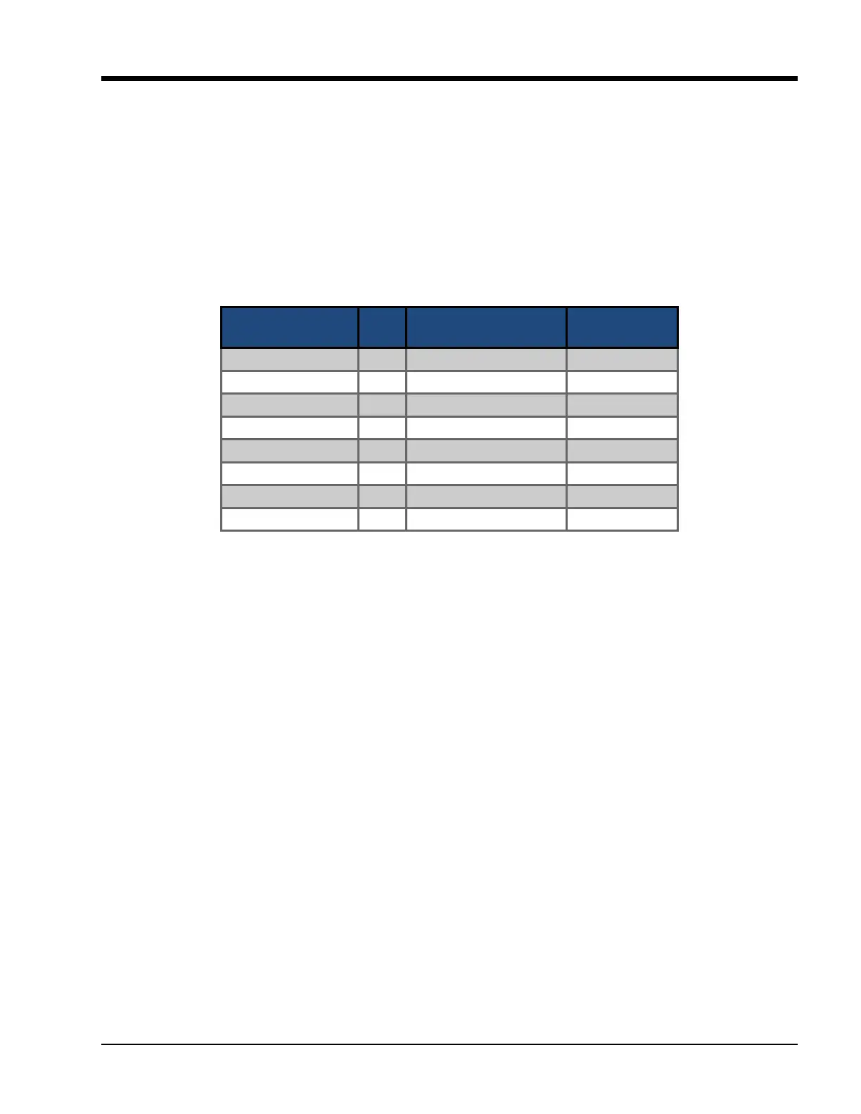
Table 2-4. Auxiliary Digital I/O)
Connector on Auxil-
iary Digital-IO Board
I/O # Descripon Channel Type
X1 – 1 1 Auxiliary Output #1 OUTPUT
X1 – 2 2 Auxiliary Output #2 OUTPUT
X1 – 3 3 Auxiliary Output #3 OUTPUT
X1 – 4 4 Auxiliary Output #4 OUTPUT
X2 – 1 5 Auxiliary Input #1 INPUT
X2 – 2 6 Auxiliary Input #2 INPUT
X2 – 3 7 Auxiliary Input #3 INPUT
X2 – 4 8 Auxiliary Input #4 INPUT