16 – 1
Section 16 • Service Options
MicroVission Controller • Operation and Service Manual • Emerson • 35391MV 1.3
Overview
The Service Option screen gives the operator the ability
to force individual digital or analog outputs ON.
This feature can be used for diagnostic purposes during
the initial setup, or when the operator suspects there´s
an issue with the outputs.
The buttons on this screen are not available while the
compressor is running.
Digital Outputs
The Digital Output buttons are momentary-toggle but-
tons. An output will be active while the operator has
his nger on the button, and will deactivate when the
operator´s nger is removed.
The operator can measure the output at the terminal
block using a multimeter, or visually check the output by
watching the LEDs located on the Multi-IO Board.
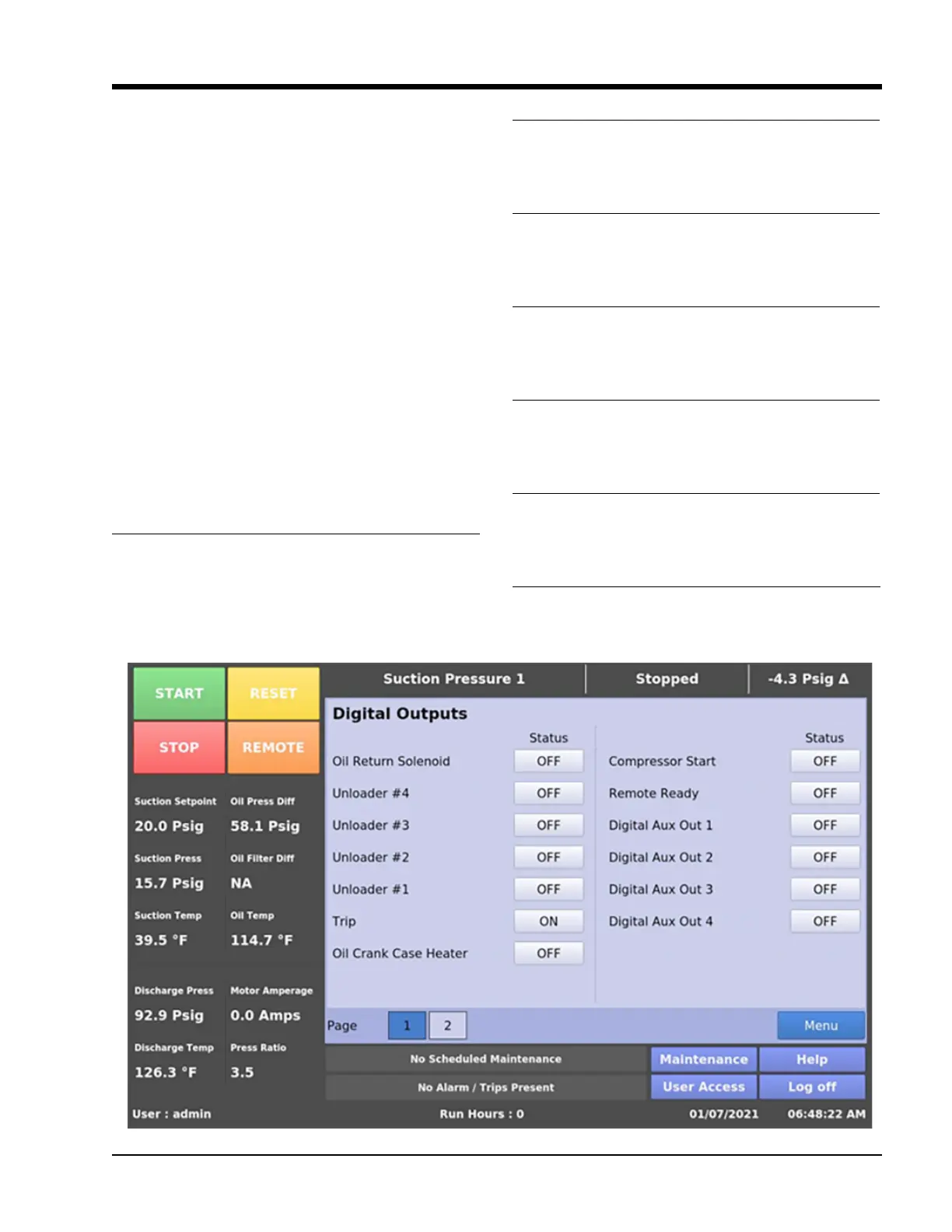
See Figure 16-1 for Digital Output screen.
Oil Return Solenoid
Activates the output assigned to the Oil Return Solenoid.
The output is connected to terminal X1-1 and is the 1st
LED on the Multi-IO Board.
Unloader #4
Activates the output assigned to the Unloader #4. The
output is connected to terminal X1-2 and is the 2nd LED
on the Multi-IO Board.
Unloader #3
Activates the output assigned to the Unloader #3. The
output is connected to terminal X1-3 and is the 3rd LED
on the Multi-IO Board.
Unloader #2
Activates the output assigned to the Unloader #2. The
output is connected to terminal X1-4 and is the 4th LED
on the Multi-IO Board.
Unloader #1
Activates the output assigned to the Unloader #1. The
output is connected to terminal X2-1 and is the 5th LED
on the Multi-IO Board.
Trip
Deactivates the output during a trip or inhibit condition.
This is an inverse acting output, connected to terminal
X2-2 and is the 6th LED on the Multi-IO Board.
Oil Crank Case Heater
Activates the output assigned to the Oil Crank Case
Heater. The output is connected to terminal X2-3 and is
the 7th LED on the Multi-IO Board.
Figure 16-1. Service Options Screen Page 1 – Digital Outputs