2 – 4
Section 2 • Hardware Architecture
MicroVission Controller • Operation and Service Manual • Emerson • 35391MV 1.3
Compressor Motor Starter Auxiliary Input:
• This input looks for a feedback signal from the com-
pressor starter, conrming that the compressor
starter is energized.
Multi-IO Board Analog I/O
For information about each Analog I/O signal, see Table
2-2. Multi-IO Board (Analog I/O).
Process Temperature
• Default signal is RTD. Process temperature calibra-
tion is set in the calibration screen.
Oil Temperature
• Default signal is RTD. Oil temperature calibration is
set in the calibration screen.
Discharge Temperature
• Default signal is RTD. Discharge temperature calibra-
tion is set in the calibration screen.
Suction Temperature
• Default signal is RTD. Suction temperature calibra-
tion is set in the calibration screen.
Filter Out Pressure
• Default signal is 4-20mA. Filter Out pressure trans-
ducer range and calibration are set in the calibration
screen.
Filter In Pressure
• Default signal is 4-20mA. Filter In pressure transducer
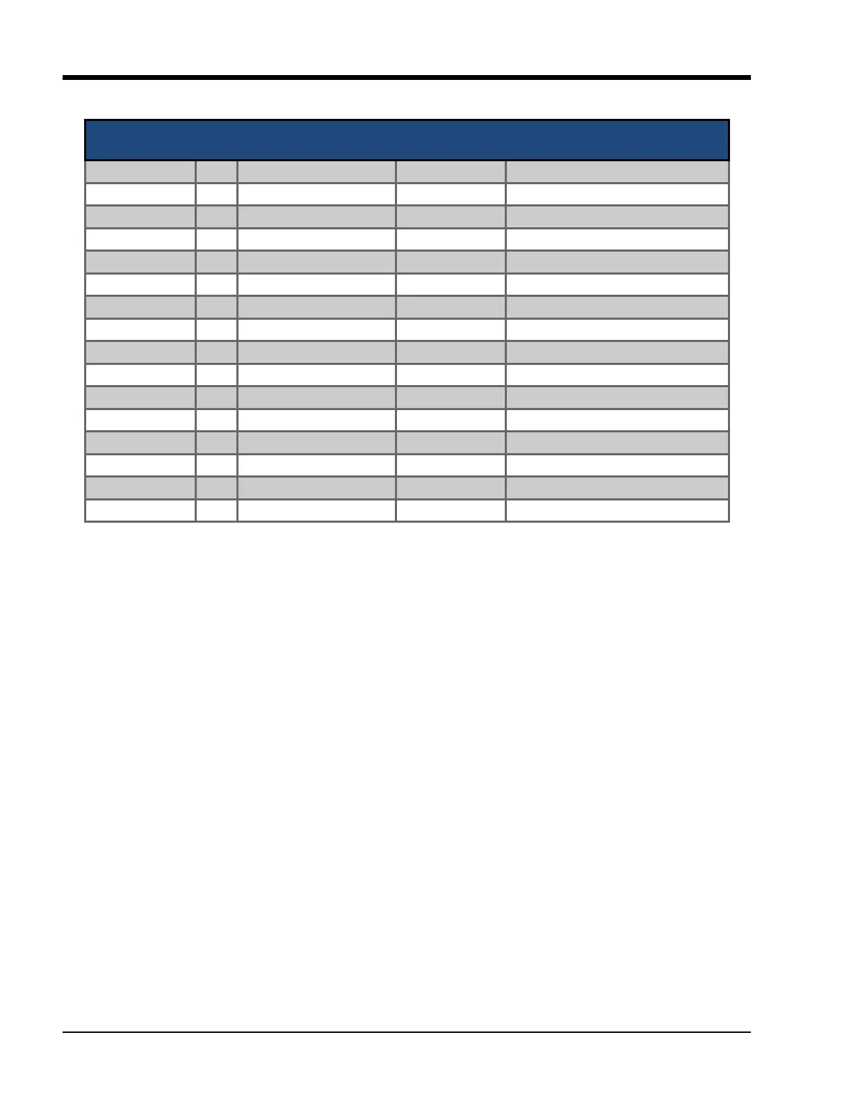
Table 2-2. Multi-IO Board (Analog I/O)
Connector on
Mul-IO Board
I/O # Descripon Channel Type Signals Type
X6 – 2 1 Process Temperature INPUT 0-5 V, 0-10 V, 4-20 mA, RTD, ICTD
X6 – 5 2 Oil Temperature INPUT 0-5 V, 0-10 V, 4-20 mA, RTD, ICTD
X7 – 2 3 Discharge Temperature INPUT 0-5 V, 0-10 V, 4-20 mA, RTD, ICTD
X7 – 5 4 Sucon Temperature INPUT 0-5 V, 0-10 V, 4-20 mA, RTD, ICTD
X8 – 2 5 Filter Out Pressure INPUT 0-5 V, 0-10 V, 4-20 mA, RTD, ICTD
X8 – 5 6 Filter In Pressure INPUT 0-5 V, 0-10 V, 4-20 mA, RTD, ICTD
X9 – 2 7 Oil Manifold Pressure INPUT 0-5 V, 0-10 V, 4-20 mA, RTD, ICTD
X9 – 5 8 Discharge Pressure INPUT 0-5 V, 0-10 V, 4-20 mA, RTD, ICTD
X10 – 2 9 Sucon Pressure INPUT 0-5 V, 0-10 V, 4-20 mA, RTD, ICTD
X10 – 5 10 Motor Amps (4-20 mA) INPUT 0-5 V, 0-10 V, 4-20 mA, RTD, ICTD
X12 – 1 11 Compressor VFD OUTPUT 4-20 mA
X12 – 3 12 Auxiliary Output #1 OUTPUT 4-20 mA
X12 – 5 13 Auxiliary Output #2 OUTPUT 4-20 mA
X13 – 1 14 Auxiliary Output #3 OUTPUT 4-20 mA
X13 – 3 15 Auxiliary Output #4 OUTPUT 4-20 mA
X13 – 5 16 Auxiliary Output #5 OUTPUT 4-20 mA
range and calibration are set in the calibration screen.
Oil Manifold Pressure
• Default signal is 4-20mA. Oil manifold pressure trans-
ducer range and calibration are set in the calibration
screen.
Discharge Pressure
• Default signal is 4-20 mA. Discharge pressure trans-
ducer range and calibration are set in the calibration
screen.
Suction Pressure
• Default signal is 4-20 mA. Suction pressure trans-
ducer range and calibration is set in the calibration
screen.
Motor Amps
• Default signal is a 4-20 mA. The Motor Amps calibra-
tion is set in the calibration screen.
Compressor VFD
• Default signal is a 4-20 mA output to control com-
pressor motor speed with a Variable Frequency Drive
(VFD).
Auxiliary Output #1 - #5:
• Optional outputs that can be congured in user de-
ned manner. When Condenser Control option is se-
lected in the conguration screen, Auxiliary Output
can be used to control Condenser VFD Fan.