20 – 9
Section 20 • Auxiliary I/O
MicroVission Controller • Operation and Service Manual • Emerson • 35391MV 1.3
Auxiliary IO Result Variables
Result Variable can be created by using available blocks
i.e. Analog Variable Block, Decision Variable Block and
Digital Variable Block. These blocks help to create a ow
chart which have result variables. “Apply” button is to
save the settings of each block. Based on the current
block the next suitable block is enabled. To delete the
block from the ow chart, the last item of the ow chart
can be deleted on press of delete button.
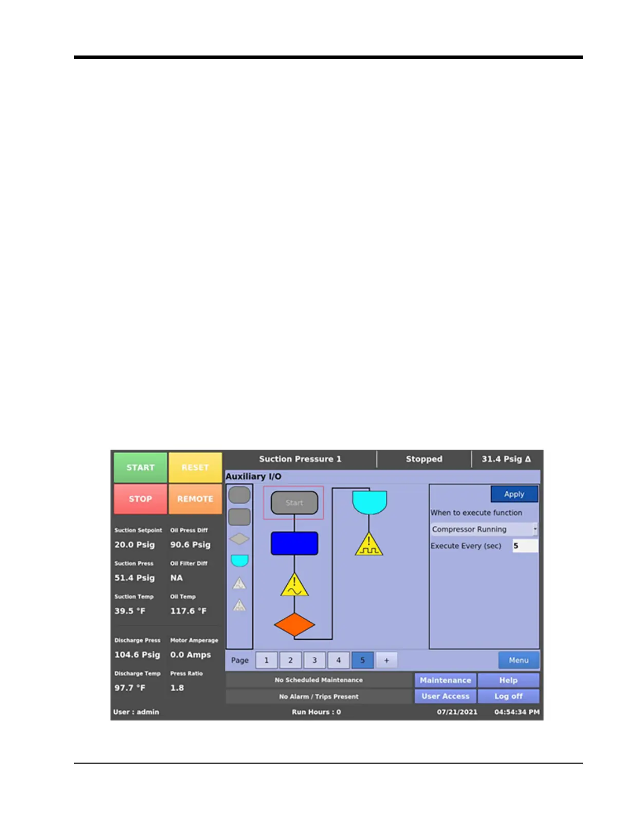
Start Block
To start the execution of the ow chart, when
“Compressor Running” the ow chart will only be ex-
ecuted when compressor is running with given interval
in seconds. When Run Always, the ow chart will be exe-
cuted always irrespective of the state of the compressor.
When Run Never, the ow chart will never be executed.
Hit Apply Button once all properties are entered, to get
next block enabled. Figure 20.8 shows the start block
properties.
Analog Variable Block
The arithmetic analog output of the given analog inputs.
The operation can be Average of two numbers, Addition,
Subtraction, Multiplication, Division and Modulo opera-
tion. The variable name must be entered and hit Apply
button to enable the next block item. Figure 20.9 shows
the properties of Analog Variable Block.
Decision Block
The Comparative output of the given analog input and
any constant value. The operation can be greater than
equal, less than equals. The variable name must be en-
tered and hit Apply button to enable the next Block item.
Figure 20.10 shows the properties of Decision Block box.
Digital Variable Block
The logical digital output of the given digital inputs. The
operation can be AND, OR, NAND, NOR, EXOR, EXNOR.
The variable name must be entered and hit Apply button
to enable the next block item. Figure 20.11 shows the
properties of Digital Variable Block box.
Analog Safety Block
The analog variable inputs can be congured to simply
monitor an input for informational purposes or used as a
control input for the analog outputs. The analog inputs
can also be congured to alarm, trip, and inhibit on spec-
ied values. Figure 20.12 shows the properties of Analog
Safety Block box.
Analog Safety Block
The digital variable input can be congured to produce
an alarm, a trip, and an inhibit on either a high or low
input. The input will simply be available to view at the
panel. Hit Apply button to enable the next block item.
Figure 20.13 shows the properties of Digital Safety Block
box.
Figure 20-8. Auxiliary I/O Screen – Result Variables – Start Properties (Page 5)