3 – 1
Section 3 • Main Screen
MicroVission Controller • Operation and Service Manual • Emerson • 35391MV 1.3
Overview
The Main screen is the rst screen displayed after pow-
ering up the MicroVission Panel. The Main screen is de-
signed as the starting point for all other screens in the
system. The interface displays the values of all important
setpoints that can help you to get the status of the com-
pressor at a glance.
The Main screen is divided into different sections such as
Top Status Bar, Bottom Status Bar, Parameters Bar and
the Splash Screen. See Figure 3-1.
Whenever you navigate to any other screen, Top Status
Bar, Bottom Status Bar and Parameters Bar will remain
visible so that operator can always view the critical infor-
mation. The Splash screen is the only dynamic section.
All navigation to any other screens will be performed
through the Main screen.
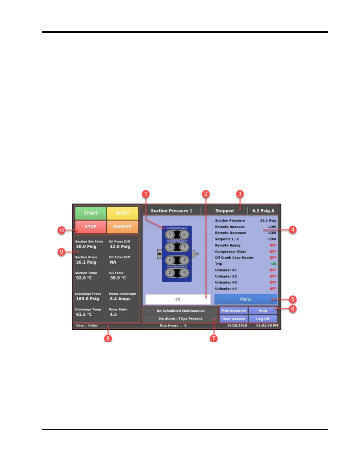
Figure 3-1. Main Screen
Information of Loaded and
Unloaded Cylinders. Loaded
Cylinders are shown in Green
Progress Bar displays the
current Capacity Utilization
of the Reciprocating
Compressor
Top Status Bar
I/O and Status
Values are displayed
as per the settings
in Conguration
Screen Page 4. For
more information,
see Conguration
section
Function buttons
to perform com-
pressor operations
Parameters Panel
Bottom status bar with user
and time information. It also
displays the Run Hours and
the currently logged In user
Information Bars
for Maintenance
Activities and Active
Safety Messages.
Menu button to
open the Menu
screen.
For more infor-
mation, see the
Menu Screen
section.
Buttons for Basic
Functions and
display help.