1 – 4
Section 1 • Installation Recommendations
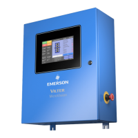
MicroVission Controller • Operation and Service Manual • Emerson • 35391MV 1.3
Best Practices
• • DoDo:
• Keep AC wires away from circuit boards.
• Always run conduit into the bottom or sides of an enclosure.
• Use a water-tight conduit tting to keep water from entering the enclosure, if the conduit must be placed
in the top of an enclosure.
• The MicroVission is supplied with pre-punched conduit holes for your use.
• Don’t:
• Do not run wires through the MicroVission enclosure that are not related to the compressor control.
• Do not add relays, timers, transformers, etc. In the MicroVission enclosure without rst checking with
Vilter
TM
.
• Do not run conduit into the top of an enclosure.
• Do not run refrigerant tubing inside the enclosure.
• Do not drill metal enclosures without taking proper precautions to protect circuit boards from damage.
Transformer, Fusing and UPS Sizing
The following information can be used to help determine the power requirements for a MicroVission panel. This infor-
mation can be helpful for sizing transformers or UPS devices that will power the MicroVission panel.
• The MicroVission panel contains a single power supply
(1) 24VDC @ 4.5 A (108 watts).
• The DC loads that are attached to the power supply are divided approximately as follows;
1. Each press transducer +24VDC @ 30 mA each (x4) = 120 mA.
2. Each RTD (negligible), (the hardware applies a 25 mA pulsed signal, which is not constant).
For estimating purposes, assume: A total sum constant draw for total RTDs used 50 mA.
3. Each 4-20mA transmitter for an RTD = 10 mA.
• So, for 120V fusing – consider 110 watts for the power supply, PLUS add any additional 120V loads that are con-
nected to the digital outputs + relays added to the panel.
1. Each unloader solenoid = 0.125 amps AC load.
2. Each small solenoid = 50 watts (estimate – read the nameplate for exact load rating).
3. Large solenoids (water, hot gas) = 100 watts (estimate– read nameplate for exact load rating).
4. Each small pilot relay = 25 watts (estimate– read the nameplate for exact load rating).
5. Add load values for panel heaters if used, and heat trace tape if used.

 Loading...


