C - 9
MicroVission Controller • Operation and Service Manual • Emerson • 35391MV 1.3
Appendix C • Remote Control and Monitoring
Control Scenario
OncetheCongurationScreenhasbeenconguredfor
the desired type of Digital I/O control, the MicroVission
needs to be placed in REMOTE mode. To do this, press
the green color START button on the main page, and
then the REMOTE button.
The Remote Start-Stop input is now active. The state of
the Remote Enable Output should be determined by the
controllingdevice.WhenitisdeterminedtobeON,then
the controlling device can energize the Remote Start-
Stop input. After the compressor has started, then the
compressor capacity is controlled by the selected op-
tion. Thought should also be given as to how the com-
pressor will be restarted after a power failure occurs.
Remote Monitoring
It should be noted that while the compressor is being
controlled (starting, stopping and load control) via hard-
wired inputs, the monitoring of compressor operating
parameters can still occur by using the communication
ports available in the MicroVission. Remote monitor-
ing can be accomplished by utilizing either the Ethernet
communication port (via Ethernet IP or Modbus TCP/
IP) or the serial port (via RS485 Modbus RTU). For com-
munication register information, refer to Appendix B:
Communication Table.
Communication Port Setup
SeeFigureC-1.CongurationScreen(Page3).
For Serial Port Modbus RTU Monitoring
• Check the “Serial” box inside the “Communications”
section.
• Congureserialportsettings(baudrate,#databits,
# stop bits, parity) and panel ID number (which is
“node” number for Modbus RTU).
For Ethernet Monitoring
• Check the “Ethernet” box inside the
“Communications” section.
• CongureIPaddressandSubnetMask.
• Select Protocol (Ethernet IP or Modbus TCP/ IP)
Once the port is setup properly, communication can be
established. You will be able to read from and write to
registers. In Direct I/O mode, you cannot write to reg-
isters in the Control Block region of Modbus registers
40170 through 40182.
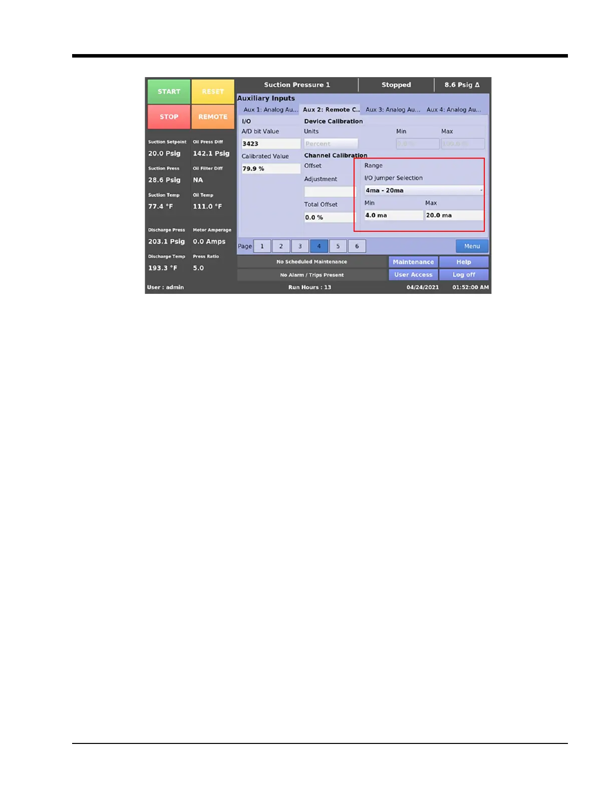
Figure C - 8. Analog Auxiliary Input (Remote Capacity %) Settings- Calibration Screen