2 – 9
Section 2 • Hardware Architecture
MicroVission Controller • Operation and Service Manual • Emerson • 35391MV 1.3
Analog Input Board I/O
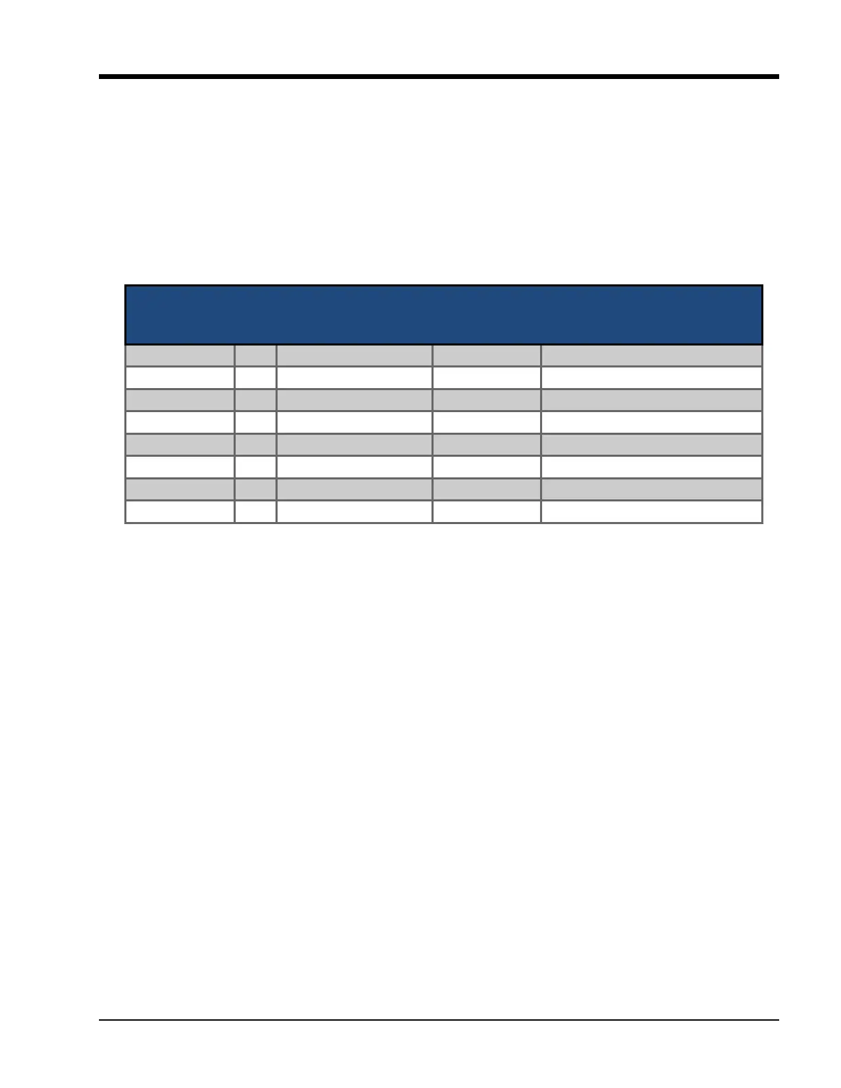
For information about each Analog input signal, see
Table 2-5. Auxiliary Analog Input.
Auxiliary Analog Input #1 - #8
• Optional analog inputs that can be congured to con-
trol, alarm or trip.
Connector on
Auxiliary Analog
Input Board
I/O # Descripon Channel Type Signals Type
X1 – 4 1 Auxiliary Input #1 INPUT 0-5 V, 0-10 V, 4-20 mA, RTD, ICTD
X1 – 7 2 Auxiliary Input #2 INPUT 0-5 V, 0-10 V, 4-20 mA, RTD, ICTD
X2 – 2 3 Auxiliary Input #3 INPUT 0-5 V, 0-10 V, 4-20 mA, RTD, ICTD
X2 – 5 4 Auxiliary Input #4 INPUT 0-5 V, 0-10 V, 4-20 mA, RTD, ICTD
X3 – 2 5 Auxiliary Input #5 INPUT 0-5 V, 0-10 V, 4-20 mA, RTD, ICTD
X3 – 5 6 Auxiliary Input #6 INPUT 0-5 V, 0-10 V, 4-20 mA, RTD, ICTD
X4 – 2 7 Auxiliary Input #7 INPUT 0-5 V, 0-10 V, 4-20 mA, RTD, ICTD
X4 – 5 8 Auxiliary Input #8 INPUT 0-5 V, 0-10 V, 4-20 mA, RTD, ICTD
Table 2-5. Auxiliary Analog Input