Multi-Function Control ETMFC610 http://www.entecene.co.kr
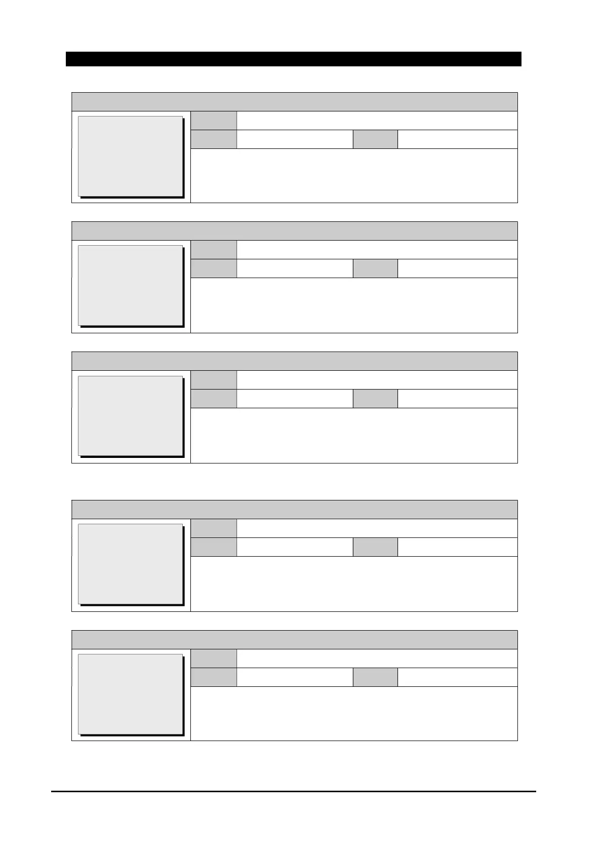
GROUP # / MONITORING / SYNCHRO’ CHECK / Min.Volt
Range
0.10~1.40 xVT
Default
0.30
Step
0.01 xVT
It sets minimum system voltage for synchronism check.
GROUP # / MONITORING / SYNCHRO’ CHECK / Max.Volt Diff
Range
0.10~1.40 xVT
Default
0.10
Step
0.01 xVT
Enter the maximum voltage difference.
A voltage magnitude differential of the two input voltages below this
value is within the permissible limit for synchronism check.
GROUP # / MONITORING / SYNCHRO’ CHECK / Angle Diff 1
Range
0(OFF), 20.0~80.0 degree
Default
30.0
Step
0.1 degree
Enter the maximum angle difference.
An angular differential between the voltage angles below this value is
within the permissible limit for synchronism check.
*. NOTE) Angle Diff 2 is same as Angle Diff 1 above.
GROUP # / MONITORING / SYNCHRO’ CHECK / Slip Freq.
Range
0.5~5.0 Hz
Default
1.0
Step
0.1 Hz
Enter the maximum slip frequency(frequency difference).
An angular differential between the frequency below this value is
within the permissible limit for synchronism check.
GROUP # / MONITORING / SYNCHRO’ CHECK / Sync Phase
Range
A, B, C, AB, BC, CA
Default
A
Step
~
Select reference voltage for synchronism check element on load side.
Function: DISABLE
Max.Volt: 1.10
>Min.Volt: 0.30
Max Volt Diff: 0.10
Angle Diff1: 30.0
[0.10~1.40:0.01 xVT]
Function: DISABLE
Max.Volt: 1.10
Min.Volt: 0.30
>Max Volt Diff: 0.10
Angle Diff1: 30.0
[0.10~1.40:0.01 xVT]
Function: DISABLE
Max.Volt: 1.10
Min.Volt: 0.30
Max Volt Diff: 0.10
>Angle Diff1: 30.0
0(OFF),20.0~80.0deg
Angle Diff2: 30.0
>Slip Freq.: 1.0
Sync Phase: A
Compens’ Angle: 0
Load-V Factor: 1.00
[0.5~5.0:0.1 Hz]
Angle Diff2: 30.0
Slip Freq.: 1.0
>Sync Phase: A
Compens’ Angle: 0
Load-V Factor: 1.00
[A/B/C/AB/BC/CA]
 Loading...