Connecting to the Network
Enterasys D-Series Hardware Installation Guide 2-29
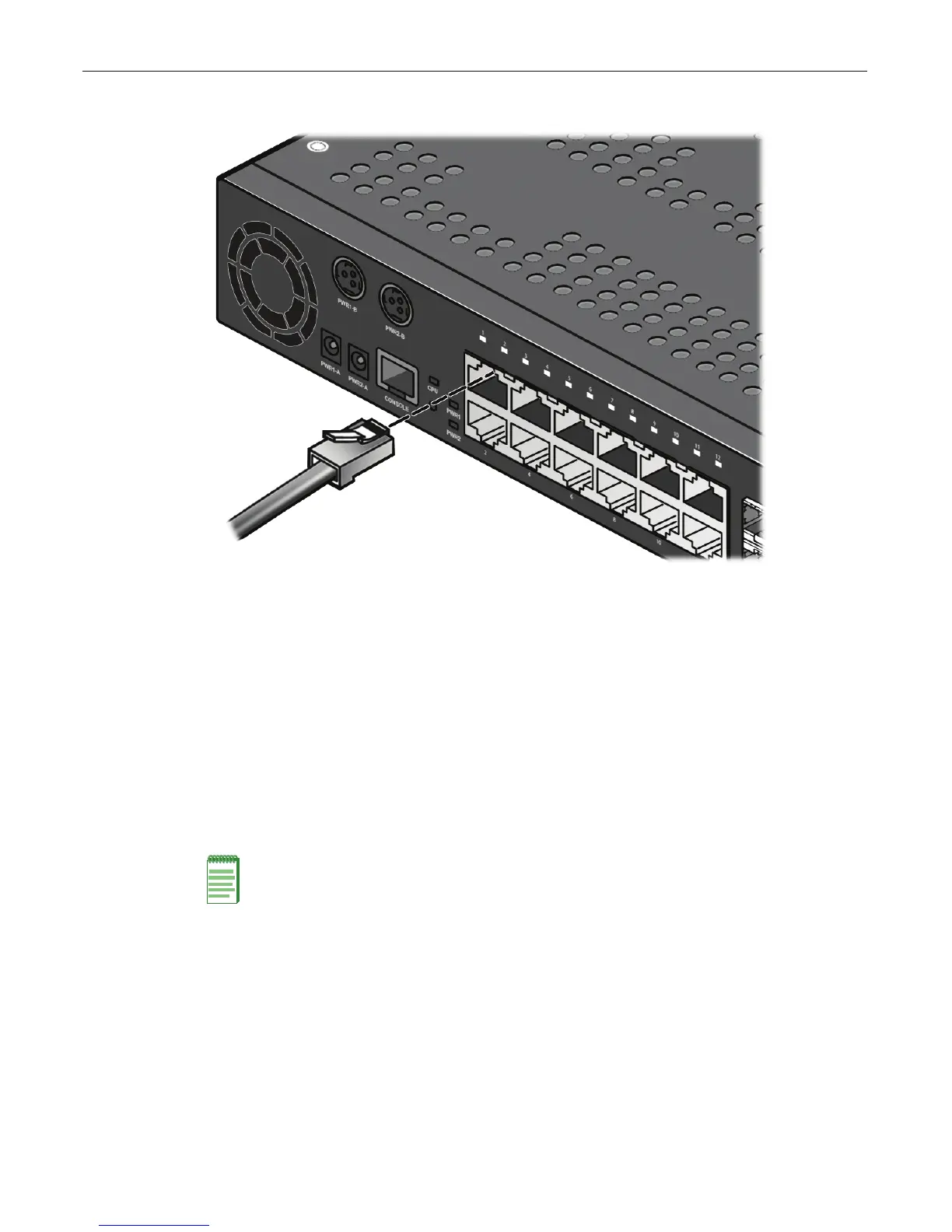
Figure 2-24 Connecting a UTP Cable Segment to RJ45 Port (D2G124-12P shown)
3. VerifythatalinkexistsbycheckingthattheLi nk/ActivityLEDison(solidgreenorblinking
green).IftheLink/ActivityLEDisoff,performthefollowingstepsuntilitison:
a. VerifythatthecablingbeingusedisCategory 5orbetterwithan impedancebetween85
and111 ohmswith
amaximumlengthof100meters(328feet).
b. Verifythatthedeviceattheotherendofthetwistedpairsegmentisonandproperly
connectedtothesegment.
4. Ifalinkisnotestablished,contactEnterasys Networks.Referto“GettingHelp”onpage xvii
fordetails.
Repeatallstepsaboveuntilall
connectionshavebeenmade.
Installing an Optional SFP
ThissectiondescribeshowtoinstallanSFPopticaltransceiverintocomboSFPports(11and12)
ontheD2G124‐12orD2G124‐12Punit
Itisrecommendedthattheoptionsbeinstalledfirstinanewinstallation.
Notes: Each combo SFP port on the D2G124-12 and D2G124-12P supports the installation of Mini-
GBICs for 1000Base-SX, 1000Base-LX, or 100Base-FX SFP transceivers.
Each combo SFP port in use on these units eliminates the availability of one RJ45 port. In other
words, only twelve ports can be active at any given time on components equipped with a
combination of RJ45 and SFP interfaces. When an SFP transceiver (Mini-GBIC) SFP port 11
establishes a link, RJ45 port 11 is disabled. When an SFP transceiver (Mini-GBIC) in SFP port 12
establishes a link, RJ45 port 12 is disabled.