Connecting to the Network
2-28 Installation
5. WhenyouarereadytobeginconfiguringtheD2switch,usetheproceduresin“Completing
theInstallation”onpage 2‐35topowerontheswitchandbootthesoftware.Youwillperform
initialsetupbyenteringCLIcommandsonthemanagementconsole.
Foradescriptionofhowtousethe
CLIanddescriptionsofalltheCLIcommands,refertothe
EnterasysD‐SeriesCLIReference.
Connecting to the Network
ThefollowingprocedurescoverthecableconnectionsfromthenetworkorotherdevicestotheD2
switch.
• ConnectingUTPCablestoRJ45Ports
• InstallinganOptionalSFPonpage 2‐29
• ConnectingFiber‐OpticCablestoSFPPortsonpage 2‐32
Connecting UTP Cables to RJ45 Ports
RJ4510000BASE‐TXfrontpanelportsontheD2G124‐12andD2G124‐12PswitchessupportAuto
MDIX,whichmeansthatyoucanusestraight‐throughorcrossovertwistedpaircabling.
ToconnecttwistedpairsegmentstotheD2,refertoFigure 2‐24onpage 2‐29andproceedas
follows:
1. Ensurethatthe
devicetobeconnectedattheotherendofthesegmentispoweredon.
2. ConnectthetwistedpairsegmenttotheD2byinsertingtheRJ45connectoronthetwistedpair
segmentintothedesiredRJ45port.
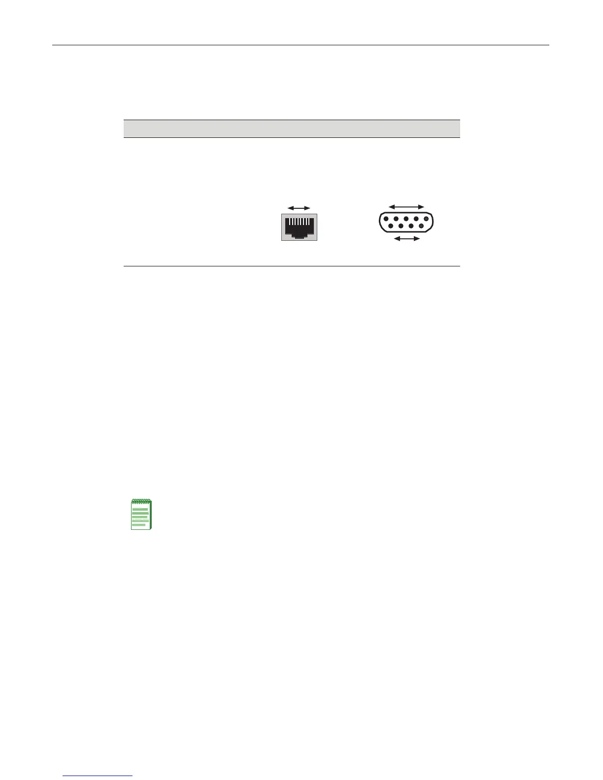
Table 2-3 RJ45 to DB9 Adapter Pinout
Signal RJ45 Pin DB9 Pin
Receive (RX) 1 2
Transmit (TX) 4 3
Ground (GRD) 5 5
RJ45 Connector (Female)
81
Pins
69
DB9 Connector (Female)
15
Pins
Note: All RJ45 front panel and IOM ports support Category 5 Unshielded Twisted Pair (UTP)
cabling with an impedance between 85 and 111 ohms. Category 3 cable may be used if the
connection is going to be used only for 10 Mbps.