Mounting the Switch
Enterasys D-Series Hardware Installation Guide 2-13
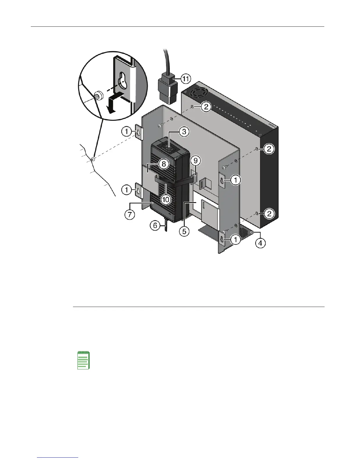
Figure 2-11 Installing the Switch On a Wall (shown with one D2-PWR supply)
1. Ensurethatyouhaveappropriatescrewsforsecuringtheassembledwallmountkittoyour
walllocation.Thesefourscrewsarerequiredandarenotprovidedinthewallmountkit.
2. Mounttheswitchonthefrontsideofthewallmountkitinthedirectionshown,aligningthe
threescrew
holesonthebottomoftheunitwiththethreeholesinthewallmounttray.
3. Usingthescrewsprovided,fastentheswitchtothewallmountingtray.
4. Installapowersupplybyslidingitundertheflangelocatedonthebottomsideofthewall
mountingtray.
1 Wall mounting screw holes (four) 7 Power supply (D2-PWR shown)
2 Switch mounting screw holes (three) 8 Power supply mounting flange
3 AC power receptacle 9 Power supply mounting bracket
4 Fan tab 10 Power supply hook & loop strap
5 Serial number access window 11 AC power cord
6
DC power cord
Note: Ensure that the D2 switch is secured to the wall mount tray in the position shown, with the
back panel of the switch facing downward. The fan tab on the wall mount tray must face downward
when the kit is installed on the wall.