Mounting the Switch
Enterasys D-Series Hardware Installation Guide 2-7
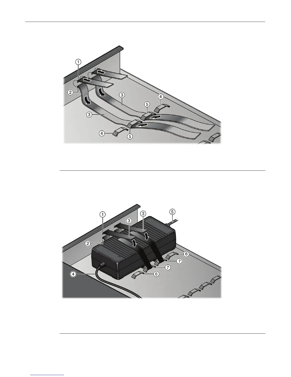
Figure 2-6 Positioning of Hook & Loop Straps to Secure Power Supply (edge of tray
shown)
2. Repeatstep 1onpage 2‐6withanotherhook&loopstraptosecuretheothersideofthepower
supplytothemountingtray.FinalplacementisshowninFigure 2‐7.
Figure 2-7 Securing a Power Supply to the Rack Mount Tray (edge of tray position shown)
1 Top power supply mounting hole 4 Outer set of bridge anchors
2 Bottom power supply mounting hole 5 Inner set of bridge anchors
3 Hook & loop straps
1 Top power supply mounting hole 5 AC power cord
2 Bottom power supply mounting hole 6 Outer set of bridge anchors
3 Hook & loop straps 7 Inner set of bridge anchors
4 DC power cord