Overview
1-2 Introduction
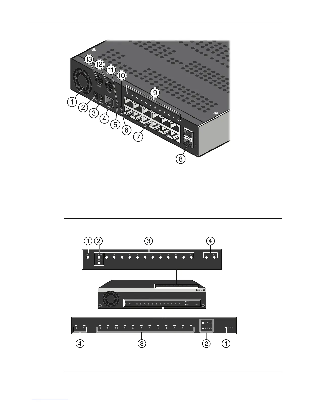
Figure 1-1 D2G124-12P Switch (rear view) without plastic cover installed
Figure 1-2 D2G124-12P Switch (top and front view) without plastic cover installed
1 Fan 8 SFP combo ports (11 and 12)
2 Power Supply 1 non-PoE receptacle (PWR1-A) 9 RJ45 Port LEDs
3 Power Supply 2 non-PoE receptacle (PWR2-A) 10 Power Supply 1 (PWR1) LED
4 Console port (RJ45) 11 CPU (system) LED
5 Reset button 12 Power Supply 2 PoE receptacle (PWR2-B)
6 Power Supply 2 (PWR2) LED 13 Power Supply 1 PoE receptacle (PWR1-B)
7
RJ45 ports (1-12)
1 CPU (system) LED 3 RJ45 port LEDs (ports 1-12)
2 Power supply (PWR1 and PWR2) LEDs 4 SFP combo port LEDs (ports 11 and 12)