Mounting the Switch
2-16 Installation
Figure 2-13 Installing the Switch in the D2 Lockbox Tray
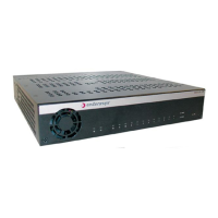
2. MounttheswitchinsidethelockboxtrayinthedirectionshowninFigure 2‐13onpage 2‐16,
aligningthethreescrewholesonthebottomoftheunitwiththethreeholesinthelockbox
tray.
3. Usingthescrewsprovided,fastentheswitchtothelockboxtray.
Installing Power Supplies
Oncetheswitchissecuredinthelockboxtray,assembletherestoftheD2componentsintothe
lockbox.IfyouareinstallingtheD2‐HIPWR‐POEpowercombinerinthelockbox,see“Installing
theD2‐HIPWR‐POEintheLockbox”onpage 2‐18.
Toinstallpowersuppliesintothe
lockbox:
1. Usingoneofthehook&loopstrapsprovided,completethefollowingstepstosecureoneend
ofthepowersupplyinthepositionshowninFigure 2‐14onpage 2‐17:
1 Mounting screws (three) 3 D2 switch fan vent
2 Mounting screw holes
Note: Ensure that the D2 switch is secured to the lockbox tray in the position shown in Figure 2-21
on page 2-23. The fan tab on the lockbox tray must face downward when the kit is installed on the
wall.

 Loading...