Completing the Installation
Enterasys D-Series Hardware Installation Guide 2-35
3. Usingthefourscrewsprovided,attachthecovertotheswitch.Fastensecurely.
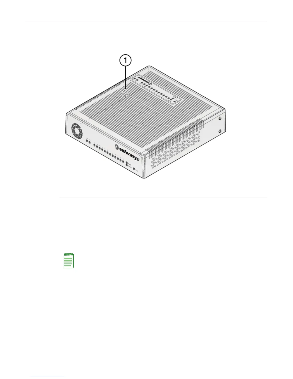
Figure 2-28 Optional Kensington Lock Opening
4. (Optional)SecuretheswitchandcoverassemblywithaKensingtonlockusingtheoptional
knock‐outopeningonthecover’ssidepanel,asshowninFigure 2‐28,andthecorresponding
slotontheD2switch.
Completing the Installation
1. Powerontheswitch.
2. VerifythatthePWR1andPWR2powerLEDsarelit.Referto“PowerLEDDisplays”on
page 2‐27forinformationoninterpretingthepowerLEDs.
3. VerifythattheCPULEDblinksinitiallythenbecomessolidgreen.
4. Makesurethatthenetworkdevicesconnectedtotheswitchports
arepoweredon,thenverify
thateachLink/Activ ityLEDisON(solidgreenorblinkinggreen).
5. Atthedeviceconnectedtotheconsoleport,performthefollowing:
a. EnteradminforUsername.
b. AtthePasswordprompt,pressENTER(RETURN).
1 Location of knock-out opening for optional Kensington lock
Note: The D2 fans turn on when power is first supplied to the switch and will shut off automatically.
The fans will turn back on automatically if the temperature ever exceeds the following ambient
thresholds:
• D2G124-12 - 40 degrees C (104 degrees F)
• D2G124-12P - 35 degrees C (95 degrees F)