SC-F2000 Revision C
ADJUSTMENT CR Related Adjustments 233
Confidential
[Blue]: Button or menu name on the program screen / [Black]: Button or menu name on the operation panel of the printer
4.10.6 Clamp Position Adjustment
REQUIRED TOOL
Scale
PROCEDURE
1. Open the printer cover.
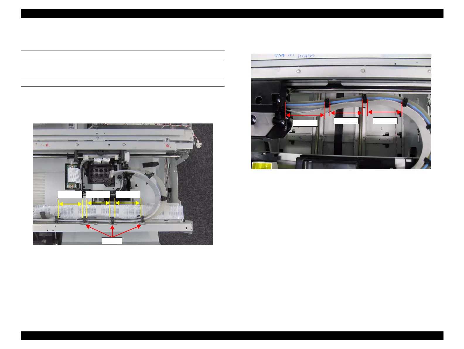
2. As shown in Figure 4-30, adjust the clamps to the center of the cutouts. The
following values are for reference only.
Figure 4-30. Positioning the Clamp
3. Release the CR lock.
4. Move the CR Unit to the full side.
5. Measure the distances of (4) to (5) shown in Figure 4-31, and adjust the clamp
positions if the distances are not the same as those values given in the figure.
Figure 4-31. Positioning the Clamp (4) to (6)
(1) 64mm (2) 72mm (3) 70mm
Cutouts
 Loading...


