SC-F2000 Revision C
DISASSEMBLY & ASSEMBLY Disassembly and Assembly Procedure 96
Confidential
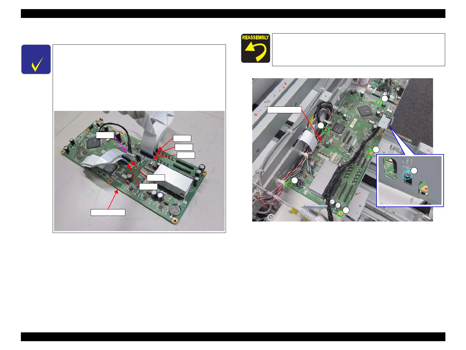
11. Disconnect cables and FFCs from the MAIN BOARD.
12. Remove the six screws, and remove the MAIN BOARD.
B) Silver M3x8 Bind machine screw: 5 pcs
C) Silver M3x4 Bind machine screw: 1 pcs
13. Disconnect the cable and FFCs from the connectors (CN200, CN201, CN300,
CN301, CN400, CN500).
Figure 3-42. Removing the MAIN BOARD
No need to disconnect the FFCs and cable connected to the
following connectors:
• CN200
• CN201
• CN300
• CN301
• CN400
• CN500
CN400
CN200
CN201
CN301
CN500
CN300
MAIN BOARD
When installing a new MAIN BOARD to the printer, first connect
the FFCs and cable to the connectors (CN200, CN201, CN300,
CN301, CN400, CN500), then install the MAIN BOARD to the
printer.
 Loading...


