EPSON Stylus CX4900/CX4905/CX5000/DX5000/DX5050/CX5900/CX6000/DX6000/DX6050 Revision A
DISASSEMBLY/ASSEMBLY Printer Section 155
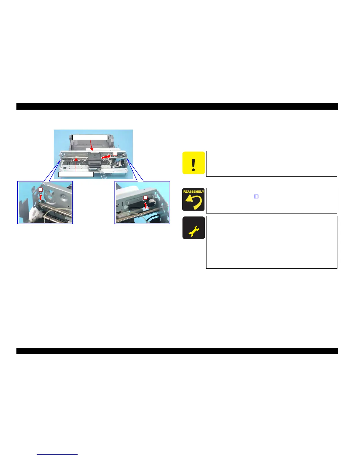
External view (2)
Figure 4-40. Removing Carriage Unit (2)
6. Remove the Carriage Unit and the Carriage Guide Shaft from Printer
Mechanism as follows.
1. Lift up the left end of the Carriage Guide Shaft and shift to the left until
the right end is released from the notch of the Main Frame.
2.
Remove the Carriage Guide Shaft and the Carriage Unit from the Main Frame.
7. Pull out the Carriage Guide Shaft from the Carriage Unit.
2
Carriage Unit
Carriage Guide Shaft
1
1
C A U T I O N
Do not damage the Carriage Guide Shaft.
Do not stain the Timing Belt with the grease.
When installing the Parallel Adjustment Lever to the Main Frame,
match the guide pin (x1,
) of the Main Frame with the positioning
hole (x1) of the Parallel Adjustment Lever (left).
A D J U S T M E N T
R E Q U I R E D
After replacing the Carriage Unit with a new one, always apply
grease G-71 to the specified parts.
• Refer to Figure 6-7 (p194) for details.
After replacing/removing the Carriage Unit, perform the
adjustment referring to
Table 5-1."Required Adjustments"
(p172)
After replacing/removing the Carriage Guide Shaft, perform the
adjustment referring to
Table 5-1."Required Adjustments"
(p172)

 Loading...


