EPSON Stylus CX4900/CX4905/CX5000/DX5000/DX5050/CX5900/CX6000/DX6000/DX6050 Revision A
DISASSEMBLY/ASSEMBLY Printer Section 156
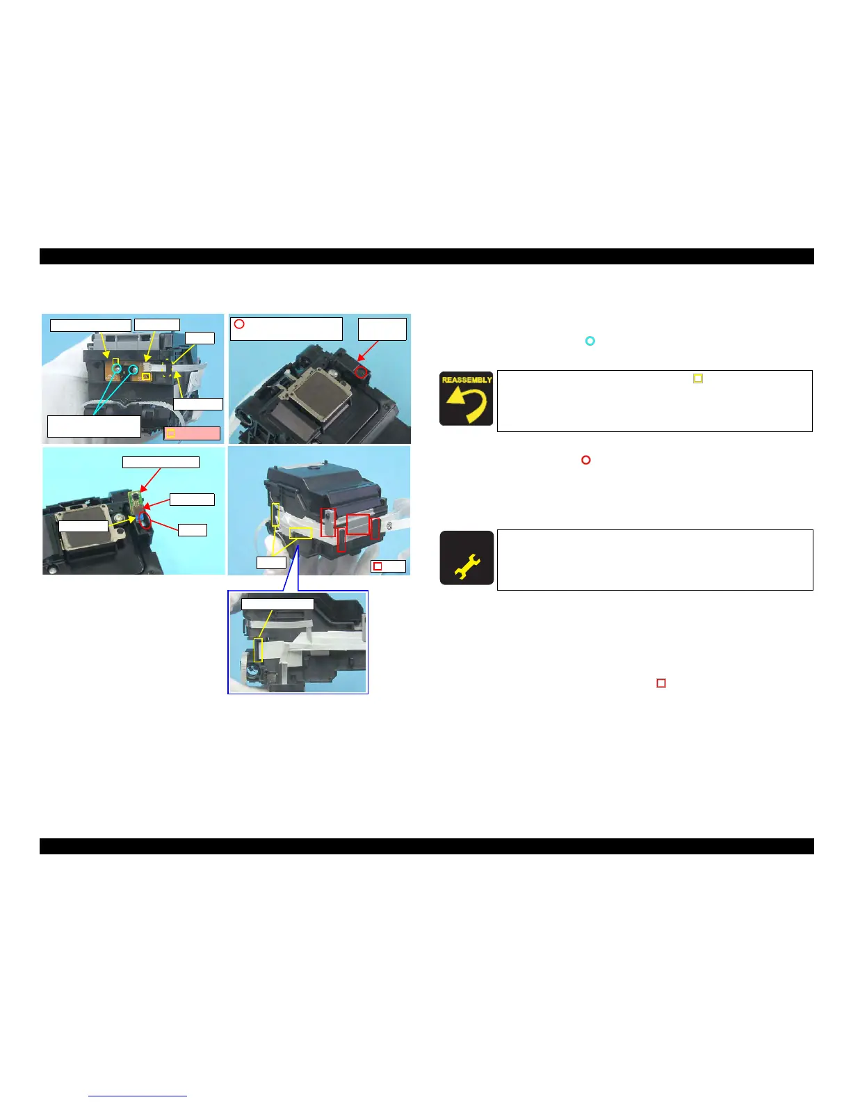
External view (3)
Figure 4-41. Removing Carriage Unit (3)
CR Encoder Removal
1. Disconnect the Head FFC from the connector of the CR Encoder Board, and
pull out the Head FFC from the notch of Carriage.
2. Remove the screws (x2, ) that secure the CR Encoder Board, and remove
the CR Encoder Board
PW S
ensor Board Removal
1. Remove the screw (x1, ) that secures the PW Sensor Cap, and remove the
PW Sensor Cap.
2. Disconnect the Head FFC from the connector of the PW Sensor Board, pull
out the Head FFC from the notch of the Carriage, and remove the PW Sensor
Board.
Head
FFC Removal
1. Remove the Printhead from the Carriage Unit.
2. Pull out the Head FFC from the notch of the Carriage.
3. Disconnect the Head FFC from the connector of the CSIC board.
4. Release the Head FFC from the tabs (x4, ) that secure the Head FFC.
Tabs
Notch
PW Sensor Board
Connector
Notch
Head FFC
PW Sensor
Cap
C.B.P. (P1) 1.7x5 F/ZB
(2±0.5kgfcm)
CR Encoder Board
Connector
Notch
Head FFC
C.P.B. (P1) 1.7x5 F/ZB
(2±0.5kgfcm)
Guide Pins
CSIC Connector
Match the guide pins of the Carriage (x2, ) with the positioning
hole (x2) of the CR Encoder Board.
A D J U S T M E N T
R E Q U I R E D
After removing/replacing the PW Sensor Board, perform the
adjustment referring to Table 5-1."Required Adjustments" (p172)

 Loading...


