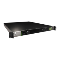
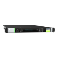
1.3 Front Panel
The front panel of the unit consists of a power switch, a confidence monitor, a light
bar, an USB Connector, a rotary knob, a main display and a keypad.
Figure 1.1 Front Panel
1.3.1 Power Switch
The mains switch is recessed to prevent accidental switch-off.
1.3.2 Confidence Monitor
The confidence monitor allows the user to monitor the selected input video signal.
Figure 1.2 Confidence Monitor
The confidence monitor is a 1.8 inch TFT LCD. The On key on the confidence
monitor turns the monitor on or off. By pressing and holding the On key, operation
related data is shown. The first line displays the total number of hours the monitor
has been operating; the second line displays the software version. The source of the
video to be displayed, the sleep timeout time and the monitor brightness can be
setup through the front panel or the web user interface. For details on how to
configure the settings for the confidence monitor see Chapter 3, Getting Started.
1.3.3 Light Bar
The light bar is green when there are no active alarms or warnings, and red if there
is a critical alarm. It is yellow if there is an active warning, minor or major alarm.