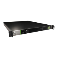
2 Installing the Equipment
Chapter 2
Contents
2.1 Read This First! ................................................................................... 2-3
2.2 Mounting and Ventilation ..................................................................... 2-3
2.2.1 Fixing and Rack Mounting ................................................................... 2-3
2.2.2 Ventilation ........................................................................................... 2-3
2.3 Signal Connections.............................................................................. 2-4
2.3.1 Rear Panel Signal Connectors ............................................................ 2-4
2.3.2 Data Ethernet Connector ..................................................................... 2-4
2.3.3 Control Ethernet Connector ................................................................. 2-5
2.3.4 CE Option Modules ............................................................................. 2-6
2.3.4.1 Digital Video Input (CE-HEVC/BNC Option Module) ............................ 2-6
2.3.4.2 Digital Video Input (CE-HEVC/SFP Option Module) ............................ 2-7
2.3.5 ASI I/O Option Card Connectors.......................................................... 2-8
2.3.6 External Sync Input Option Card Connector ........................................ 2-8
2.3.7 GPI Option Card Connector ................................................................. 2-9
2.3.8 Mini USB Connector .......................................................................... 2-10
List of Figures
Figure 2.1 Air-Flow through the Equipment .......................................................... 2-3
Figure 2.2 ASI I/O Option Card ............................................................................. 2-8
Figure 2.3 External Sync Input Option Card ......................................................... 2-8
Figure 2.4 Mini USB Connector .......................................................................... 2-10
List of Tables
Table 2.1 Data Ethernet Connector ..................................................................... 2-4
Table 2.2 Link Speed: Left (Green) LED ............................................................. 2-5
Table 2.3 Link Activity: Right (Yellow) LED.......................................................... 2-5
Tabl
e 2.4 Control Ethernet Connector ................................................................. 2-5
Table 2.5 Port Status: Left (Green ) LED ............................................................. 2-6
Table 2.6 Link Activity: Right (Yellow ) LED ......................................................... 2-6
Table 2.7 Digital Video Input via the SDI Interface .............................................. 2-7
Table 2.8 Lock LED State Descriptions ............................................................... 2-7
Table 2.9 ASI I/O Option Card Connectors.......................................................... 2-8
Table 2.10 External Sync Input Option Card Connector ........................................ 2-8

 Loading...