2.3 Signal Connections
2.3.1 Rear Panel Signal Connectors
Caution!
It is strongly recommended that the terminal marked at the rear panel of the
equipment is connected to a site Technical Earth before any external connections
are made and the equipment is powered. This limits the migration of stray charges.
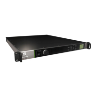
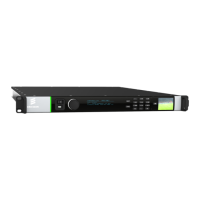
Signal connections are made via the rear panel. The rear panels, which are
available are shown below. Full technical specifications for the connections are
given in Annex B.
Only the Data and Control Ethernet connectors and the PSU connectors are
mounted on the chassis. All other connections at the rear panel are provided with
the option modules that may be fitted.
2.3.2 Data Ethernet Connector
The unit has four Ethernet ports - two for data input, and
two for data output and will respond to ARPs, pings and
other low-level Ethernet traffic. The ports are accessible
via RJ-45 connectors on the rear panel of the chassis.
These are labeled Ge 1, Ge 2, Ge 3 and Ge 4. Ge 1 and
Ge 2 are used for data input, while Ge 3 and Ge 4 are
data output.
Table 2.1 Data Ethernet Connector
Item Specification
Connector type RJ-45 (100/1000 Base T)
Connector designation Ge 1 (data input)
Ge 2 (data input)
Ge 3 (data output)
Ge 4 (data output)
Pin outs
(Unused pins are not connected)
Pin 1 - Tx Out (+)
Pin 2 - Tx Out (-)
Pin 3 - Rx In (+)
Pin 6 - Rx In (-)
Status and Activity Indication
Each Ethernet Data Port has a rear panel mounted status LED associated with it to
indicate link status, activity and speed as follows: