Security
HMG-838PT & HMG-838EPT Web Configuration 5-9
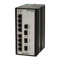
After completing all the trap settings, click the "Save" button.
Alarm Relay:
Power: Indicates the Power group's alarm relay. Possible options are:
Power 1 Status: Select the checkbox to enable Power 1 status alarm relay function. Once power 1 fails, the alarm
relay contacts are open and Fault LED indicator is on in amber. Clear the checkbox to disable Power 1 status
alarm relay.
Power 2 Status: Select the checkbox to enable Power 2 status alarm relay function. Once power 2 fails, the alarm
relay contacts are open and Fault LED indicator is on in amber. Clear the checkbox to disable Power 2 status
alarm relay.
Interface: Indicates the Interface group's alarm relay. Possible options are:
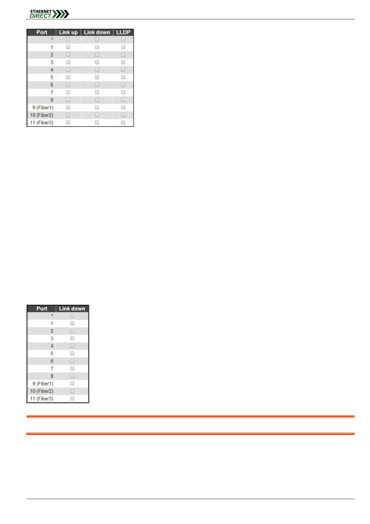
Link Down: none/specific/all ports Link down alarm relay. Once link down occurs on the selected interfaces, the
alarm relay contacts are open, Fault LED indicator is on in amber. Clear the checkbox to disable alarm relay
function.
When the "specific" radio button is selected, a popup graphic with port checkboxes allows selection specific ports.
Note: For more information about alarm relay circuit on the terminal block, please check the Hardware & Installation User’s Manual
5-1.7.3 SNMPv3 Community Configuration
Configure SNMPv3 community table on this page. The entry index key is Community.
 Loading...