Operating Instructions
Modular Safety Control System MSC
156
(Translation of the original operating instructions) 2121331-04-04/19
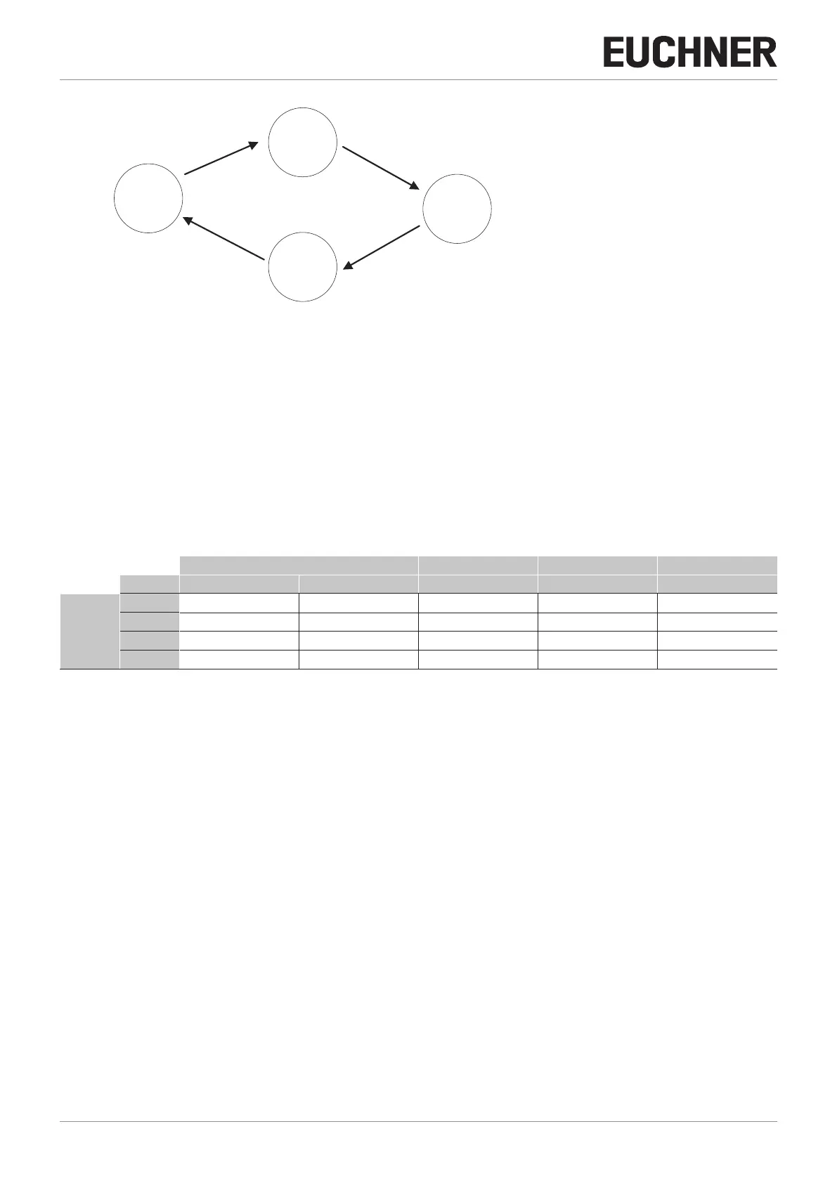
12,6 ms
164 ms
376 ms
ms
Base
unit
1
Base
unit
4
Base
unit
2
Base
unit
3
Figure 189: Response time of the network
Condition 3: If the IN input on the network function block on one of the 4 nodes switches to the state "0" (FALSE), see
Figure 188
1. The local output changes to the state "0" (FALSE).
2. The RUN signal continues to be sent via the Network_OUT lines.
3. The states of the other nodes remain unchanged.
4. In this event the local reset method must be used. The Reset_in LED flashes to indicate this state. The related node can
be restarted using its reset.
The Reset_In and Network_IN inputs and the Network_OUT output can only be represented on the I/O terminals of the
base unit.
Network IN Network OUT (OSSD) Network OUT (STATUS) Reset in
LED FAIL EXT IN (1) OSSD (2) STATUS IN (3)
STATE
STOP OFF OFF RED OFF OFF
CLEAR OFF FLASHING RED/GREEN (FLASHING) FLASHING FLASHING
RUN OFF ON GREEN ON ON
FAIL ON FLASHING – – –
(1) Corresponds to the input that is connected to Network IN.
(2) Corresponds to the input that is connected to Network OUT.
(3) Corresponds to the input that is connected to Reset IN.
Table 76: Signals of the "NETWORK" function block