Operating Instructions
Modular Safety Control System MSC
32
(Translation of the original operating instructions) 2121331-04-04/19
7.2.4. OSSD (AC-FO2, AC-FO4)
The OSSD outputs (Output Signal Switching Device) are short circuit proof and supply:
Ì In the ON state: U
V
- -0.75 V – U
V
(where U
V
= 24 V ± 20 %)
Ì In the OFF state: 0 V – 2 V eff.
The maximum load of 400 mA at 24 V corresponds to a minimum ohmic load of 60 Ω.
The maximum capacitive load is 0.82 µF; the maximum inductive load 30 mH.
NOTICE
It is not allowed to connect external devices to the outputs, except if this arrangement is foreseen in
the configuration undertaken in the software EUCHNER Safety Designer.
Each OSSD output can be configured as shown in Table 18:
Automatic
The output is only activated, as per the configuration defined by the software EUCHNER Safety Designer, if 24 VDC are applied to the related
input RESTART_FBK.
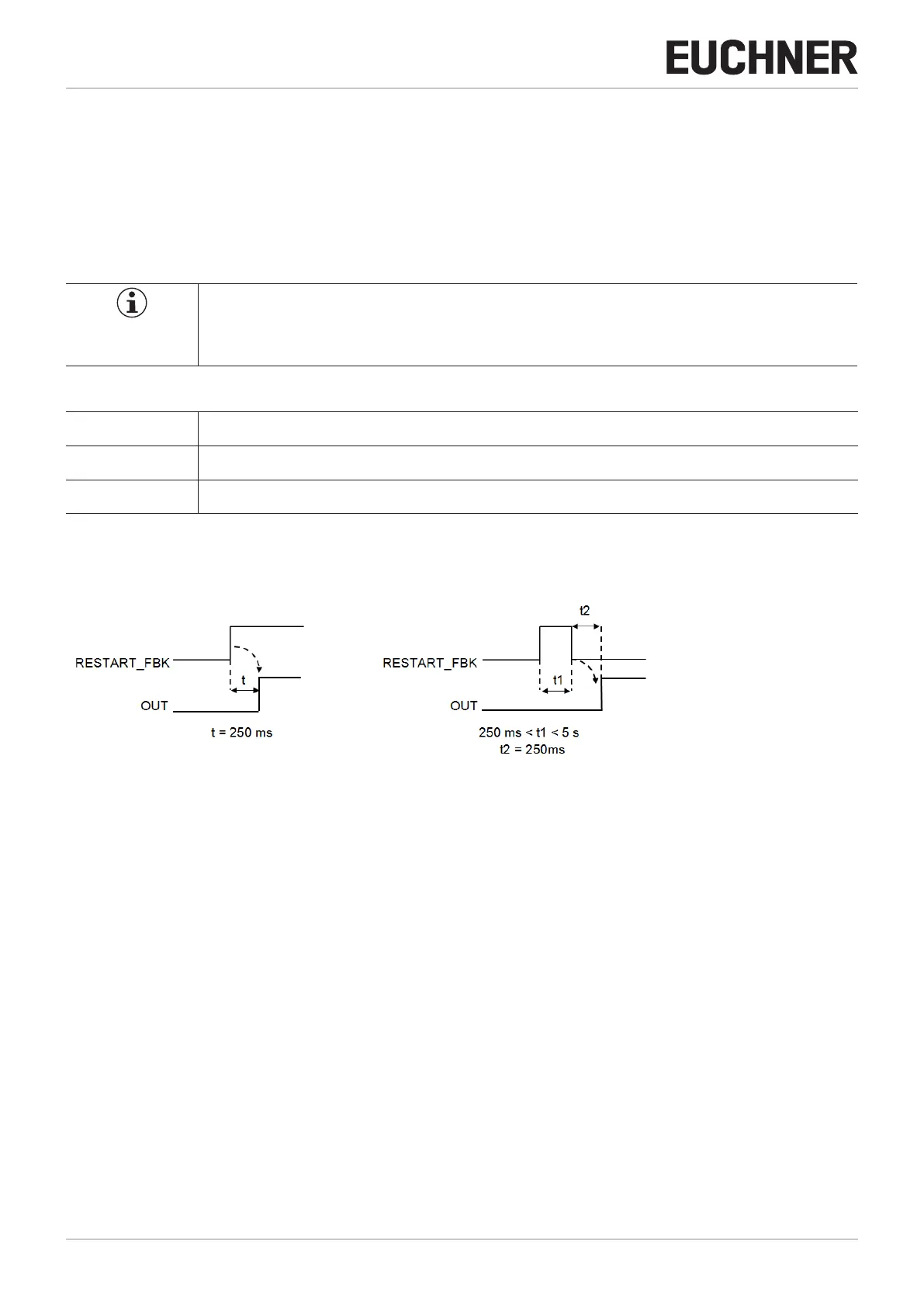
Manual
The output is only activated, as per the configuration defined by the software EUCHNER Safety Designer, if there is the logical transition 0-->1
on the related input RESTART_FBK.
Monitored
The output is only activated, as per the configuration defined by the software EUCHNER Safety Designer, if there is the logical transition 0--
>1-->0 on the related input RESTART_FBK.
Table 18: OSSD output configuration
Manual Monitored
Figure 10: Manual/monitored restart