85
2121331-04-04/19 (Translation of the original operating instructions)
Operating Instructions
Modular Safety Control System MSC
EN
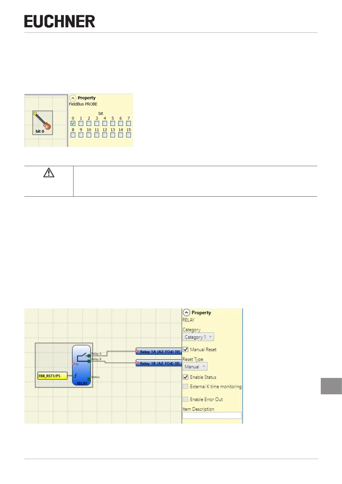
9.2.1.4. Fieldbus sensor (FIELDBUS PROBE)
Using this element, the status of any point on the diagram can be indicated on the fieldbus.
Up to 16 sensors can be used; the bit used to indicate the state must be entered for each sensor.
The states are indicated on the fieldbus using two bytes. (You will find more detailed information in the fieldbus manual on
the CD ROM "EUCHNER Safety Designer".)
Figure 72: Fieldbus probe
Important!
The FIELDBUS OUTPUT is NOT a safety output.
9.2.1.5. Relay [RELAY]
The output relay is a relay output with a normally open contact. The relay outputs are closed if the IN input is "1" (TRUE),
otherwise the contacts are open (FALSE).
Parameter
Category: there are three categories of relay outputs:
Category 1. Outputs with a category 1 relay. Each module AZ-FO4 / AZ-FO4O8 can have up to four outputs.
Properties:
Ì Internal relays are monitored.
Ì External device monitoring contacts (EDM, check on FBK 1-4) are not used (not required for category 1).
Ì Each output can be set to manual or automatic starting.
Figure 73: Relay output