21
2121331-04-04/19 (Translation of the original operating instructions)
Operating Instructions
Modular Safety Control System MSC
EN
5.3.3.9. Modules SPM0 – SPM1 – SPM2
TERMINAL SIGNAL TYPE DESCRIPTION VERSION
1 24 VDC - Power supply 24 VDC -
2 NODE_SEL0 Input
Node selection Input ("type B" as per EN 61131-2)
3 NODE_SEL1 Input
4 GND - Power supply 0 VDC -
5 PROXI1_24V Output
Connections for the 1st proximity switch
(see Page 29)
Power supply 24 VDC on PROXI1
6 PROXI1_REF Output Power supply 24 VDC on PROXI1
7 PROXI1 IN1 (3 WIRES) Input PROXI1 NO contact
8 PROXI1 IN2 (4 WIRES) Input PROXI1 NC contact
9 PROXI2_24 V Output
Connections for the 2nd proximity
switch
(see Page 29)
Power supply 24 VDC on PROXI2
10 PROXI2_REF Output Power supply 24 VDC on PROXI2
11 PROXI2 IN1 (3 WIRES) Input PROXI2 NO contact
12 PROXI2 IN2 (4 WIRES) Input PROXI2 NC contact
13 n.c. -
Not connected -
14 n.c. -
15 n.c. -
16 n.c. -
Table 9: Modules SPM0 – SPM1 – SPM2
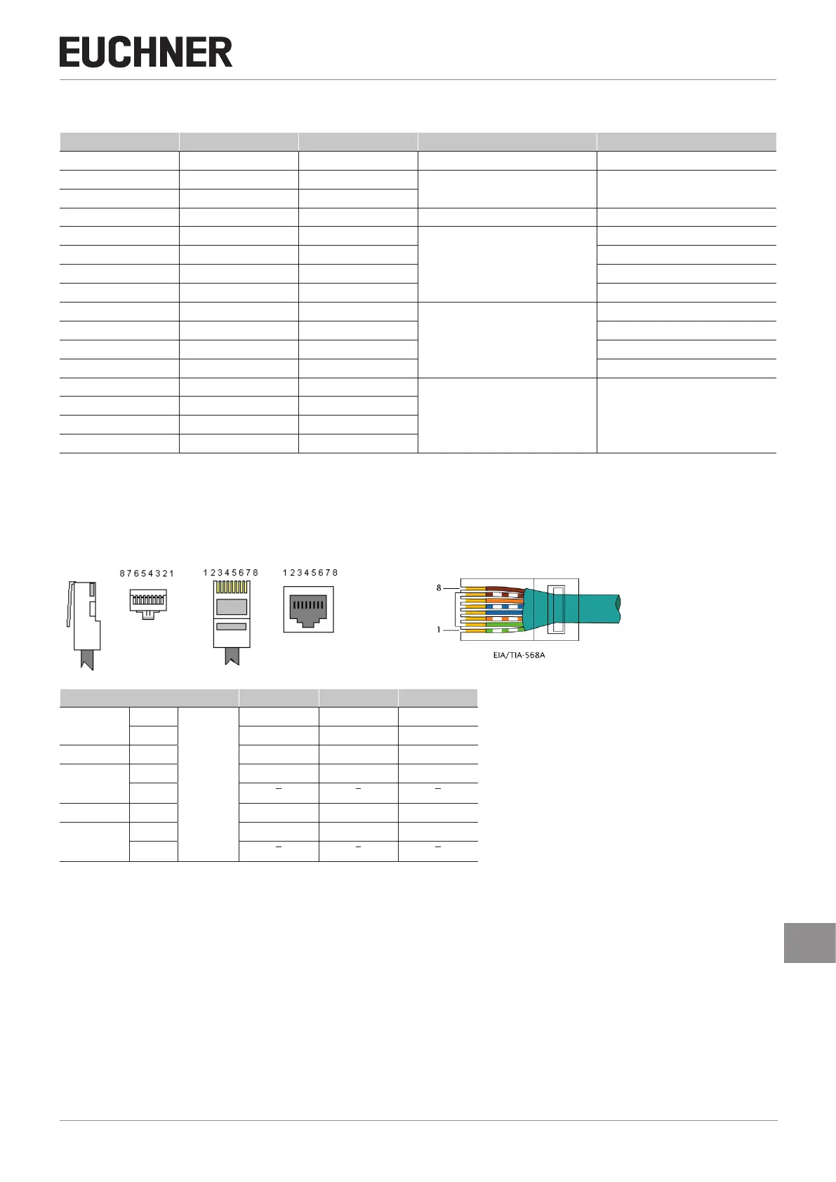
5.3.4. Encoder connections with RJ45 plug connector (SPM1, SPM2)
Pin SPMTB SPMH SPMH
TWISTED *
1
INPUT
n.c. n.c. n.c.
2 GND GND GND
3 n.c. n.c. n.c.
TWISTED *
4 A A A
5
A A A
6 n.c. n.c. n.c.
TWISTED *
7 B B B
8
B B B
* If twisted-pair cables are used.
Table 10: PIN assignment